hmmmniek
1 mW
- Joined
- May 5, 2022
- Messages
- 13
Hey! I've been lurking the forums for a little while now, since I have been planning a conversion of an XJR 1300 for a while in my spare time.
Now I will finally have a bunch of spare time to work on this project. All the parts are in, and the plans for the battery build are pretty much finalized.
Battery build is part one of my project. I intend to keep this thread alive with regular updates for a long time. Since I know this project will take me a long time to finish.
The plans for the battery build are pretty much done, but other details about this project are not entirely finalized yet. My approach to this project is to divide-and-conquer. Battery building is step 1. After that, I will focus on testing all electronics. Making a minimum viable product. And continuing from there.
When I say plans for battery build are done. What I actually mean is that plans for the first layer of the battery are finished and ready to be assembled.
I am planning to build 4 separate 35S 18650 battery packs. With varying capacities, connected in parallel. Controlled by a single BMS.
I like documenting in detail, so let's start from the beginning.
Part 1; Designing
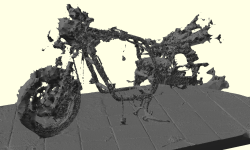
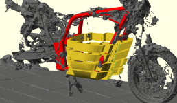
I bought this XJR 1300 second hand. It still ran well, but now I have sold the engine and a bunch of other parts. So I am committed to the project now Using RealityScan, I created a simple 3D model of the disassembled motorcycle.
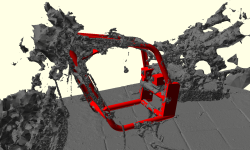
Using this model, I can overlay a simplified and representation of the relevant section of the frame. I do all the 3D designing using OpenSCAD. As a software engineer, this software felt the most intuitive.
Now, I already knew the specifications for the battery pack that I wanted to build. It was going to be a 35S45P pack. This is determined based on the max voltage rating of my chosen components, and a conservative range estimate of 200km highway speeds.
I just needed to figure out how to fit all the batteries into this frame. It will be a large pack. So finding the right shape is a challenge.
I had some criteria;
1 - It should have airflow going through it. I can't water-cool the pack because of practical constraints, so air-cooling is the best I can do.
2 - It should be mounted decently, preferably using existing engine-block mounting points.
3 - It should not block any components (handlebars, sidestand etc)
4 - It should leave enough space for controller, BMS, on board charger, dc-dc converter, circuit breaker (optional; storage space)
5 - It should look somewhat decent, "aerodynamic"
6 - It should not be too wide for your knees
Because my desire to build a pack with enough airflow, I felt I had 2 options. Either build vertical pack layers, or horizontal layers.
Exploring vertical layers using some basic paint mockups, made me realize that fulfilling criteria 2 and 4 would be difficult.
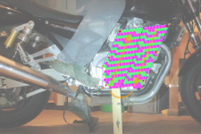
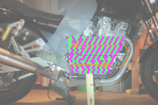
So I started exploring horizontal layers in OpenSCAD. Unfortunately don't have any saved screenshots from this process. But I noticed that it would probably be possible to fit a 35S45P pack into the frame, when split up into 4 parallel packs.
1x 35S7P, 1x 35S10P, 2x 35S14P.
All 18650 cells that I bought are capacity tested and labeled. So if I correctly spread out the varying capacities of the cells. Then in theory the pack will barely "notice", that it is actually 4 separated packs connected in parallel. Even though the parallel groups will be split up into 4 parts, I will make sure that every parallel group is still electrically connected to each other with some external wiring/connectors. This way, the capacity between the cells in a single group will not start varying. This way, it is still technically a single 35S45P pack, but they can be assembled in 4 parts.
Another advantage of splitting up the pack into 4 parts, is that I can assemble a first layer, which will give me the necessary voltage to already start testing other electronics. Albeit with lower capacity and limited amperage.
After a while of fiddling about in CAD. I came to the following base shape which would fit my criteria pretty well.
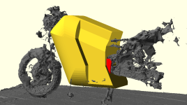
Split up into layers, It would look as follows. The top 2 layers are still not finalized. The second from the top layer, will probably house all electronics, controller, BMS etc. The very top layer could be used for a small amount of additional storage (a glove box, if you will).
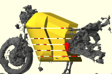
Using a digital drawing tool, I figured out some ways to organize the groups within each supposed battery layer. Optimizing for as much "parallel contact" as possible between each group. Of course this is not possible everywhere, because of strange shapes that I ended up with. However, I see it as a fun challenge to build this battery pack as compact as possible. It will not be possible to have groups of simple straight rows everywhere.

Next, we can start "hollowing out" the layers. Making space for the cells. Also adding points for external connectors (power, thermistors, and pack voltage balancing connections) And at the same time we can start modeling space in the layers for mounting points.
Removing the scan now to remove clutter. Mounting the battery pack layers will be done by "squeezing" the pack in between EP GC 202 (FR4) sheets. These sheets are then supported on 4 corners using steel tubes which will be attached to the original engine mounts.
I chose the glass cloth reinforced epoxy sheet material, since it is a good electrical insulator. Weather and impact resistant. And most importantly, has a high flexural strength, which has the best chance of holding the weight of all these batteries in a secure manner.
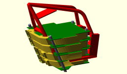
After all of this preparation. We can focus on the first (bottom, and smallest) battery pack layer.
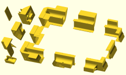
We split it up in 3D-printable sections. Add assembly holes. Space for internal wiring. Space for structural rods that help to keep the pack together.
End of part 1
In reality, I am already a bit further ahead than what I am writing in this initial post. The first battery pack layer parts have been 3D printed. The copper sheets that will be used to connect the cells have been cut out in their correct shapes. And I am currently organizing and pre-balancing the cells before starting with spot-welding the first pack layer together. I will write another update post about this process after a while when I feel like I have reached another meaningful milestone.
The designing step is done for the first battery pack layer. But is still not finished for layer 2, 3 and 4. My plan is to assemble the first layer. Then use that first layer to test all electronics. And maybe build a first version of the motorcycle with limited capacity and 1/6th limited power.
After that all seems to work, I will be able to start building the next layers, slowly increasing the available power of the motorcycle build.
Now I will finally have a bunch of spare time to work on this project. All the parts are in, and the plans for the battery build are pretty much finalized.
Battery build is part one of my project. I intend to keep this thread alive with regular updates for a long time. Since I know this project will take me a long time to finish.
The plans for the battery build are pretty much done, but other details about this project are not entirely finalized yet. My approach to this project is to divide-and-conquer. Battery building is step 1. After that, I will focus on testing all electronics. Making a minimum viable product. And continuing from there.
When I say plans for battery build are done. What I actually mean is that plans for the first layer of the battery are finished and ready to be assembled.
I am planning to build 4 separate 35S 18650 battery packs. With varying capacities, connected in parallel. Controlled by a single BMS.
I like documenting in detail, so let's start from the beginning.
Part 1; Designing
I bought this XJR 1300 second hand. It still ran well, but now I have sold the engine and a bunch of other parts. So I am committed to the project now

Using this model, I can overlay a simplified and representation of the relevant section of the frame. I do all the 3D designing using OpenSCAD. As a software engineer, this software felt the most intuitive.

Now, I already knew the specifications for the battery pack that I wanted to build. It was going to be a 35S45P pack. This is determined based on the max voltage rating of my chosen components, and a conservative range estimate of 200km highway speeds.
I just needed to figure out how to fit all the batteries into this frame. It will be a large pack. So finding the right shape is a challenge.
I had some criteria;
1 - It should have airflow going through it. I can't water-cool the pack because of practical constraints, so air-cooling is the best I can do.
2 - It should be mounted decently, preferably using existing engine-block mounting points.
3 - It should not block any components (handlebars, sidestand etc)
4 - It should leave enough space for controller, BMS, on board charger, dc-dc converter, circuit breaker (optional; storage space)
5 - It should look somewhat decent, "aerodynamic"
6 - It should not be too wide for your knees
Because my desire to build a pack with enough airflow, I felt I had 2 options. Either build vertical pack layers, or horizontal layers.
Exploring vertical layers using some basic paint mockups, made me realize that fulfilling criteria 2 and 4 would be difficult.


So I started exploring horizontal layers in OpenSCAD. Unfortunately don't have any saved screenshots from this process. But I noticed that it would probably be possible to fit a 35S45P pack into the frame, when split up into 4 parallel packs.
1x 35S7P, 1x 35S10P, 2x 35S14P.
All 18650 cells that I bought are capacity tested and labeled. So if I correctly spread out the varying capacities of the cells. Then in theory the pack will barely "notice", that it is actually 4 separated packs connected in parallel. Even though the parallel groups will be split up into 4 parts, I will make sure that every parallel group is still electrically connected to each other with some external wiring/connectors. This way, the capacity between the cells in a single group will not start varying. This way, it is still technically a single 35S45P pack, but they can be assembled in 4 parts.
Another advantage of splitting up the pack into 4 parts, is that I can assemble a first layer, which will give me the necessary voltage to already start testing other electronics. Albeit with lower capacity and limited amperage.
After a while of fiddling about in CAD. I came to the following base shape which would fit my criteria pretty well.

Split up into layers, It would look as follows. The top 2 layers are still not finalized. The second from the top layer, will probably house all electronics, controller, BMS etc. The very top layer could be used for a small amount of additional storage (a glove box, if you will).

Using a digital drawing tool, I figured out some ways to organize the groups within each supposed battery layer. Optimizing for as much "parallel contact" as possible between each group. Of course this is not possible everywhere, because of strange shapes that I ended up with. However, I see it as a fun challenge to build this battery pack as compact as possible. It will not be possible to have groups of simple straight rows everywhere.

Next, we can start "hollowing out" the layers. Making space for the cells. Also adding points for external connectors (power, thermistors, and pack voltage balancing connections) And at the same time we can start modeling space in the layers for mounting points.

Removing the scan now to remove clutter. Mounting the battery pack layers will be done by "squeezing" the pack in between EP GC 202 (FR4) sheets. These sheets are then supported on 4 corners using steel tubes which will be attached to the original engine mounts.
I chose the glass cloth reinforced epoxy sheet material, since it is a good electrical insulator. Weather and impact resistant. And most importantly, has a high flexural strength, which has the best chance of holding the weight of all these batteries in a secure manner.

After all of this preparation. We can focus on the first (bottom, and smallest) battery pack layer.
We split it up in 3D-printable sections. Add assembly holes. Space for internal wiring. Space for structural rods that help to keep the pack together.

End of part 1
In reality, I am already a bit further ahead than what I am writing in this initial post. The first battery pack layer parts have been 3D printed. The copper sheets that will be used to connect the cells have been cut out in their correct shapes. And I am currently organizing and pre-balancing the cells before starting with spot-welding the first pack layer together. I will write another update post about this process after a while when I feel like I have reached another meaningful milestone.
The designing step is done for the first battery pack layer. But is still not finished for layer 2, 3 and 4. My plan is to assemble the first layer. Then use that first layer to test all electronics. And maybe build a first version of the motorcycle with limited capacity and 1/6th limited power.
After that all seems to work, I will be able to start building the next layers, slowly increasing the available power of the motorcycle build.


