10S custom skate ESC: testers wanted!

Is it possible to use 2 different versions of VESC together? I currently have the (4.09? version - from enertion with a red pcb) is that compatible with the newer 4.10? controlled over splited servo wires.
If yes: do I have to use same capacitors on both Vesc's?
 
Nordle said:
Is it possible to use 2 different versions of VESC together? I currently have the (4.09? version - from enertion with a red pcb) is that compatible with the newer 4.10? controlled over splited servo wires.
If yes: do I have to use same capacitors on both Vesc's?

Completely compatible when using a split servo wire.
 
UART could cuase problems in this case?
If they have different capacitors, will they perform equal or slightly different?
 
chaka said:
They will work fine with different capacitors on each VESC. You may be able to link them with the canbus port too? I would need to test this to confirm.
Thx you're da man!
I read a lot about burned drv chips, and most of those people had connected their VESC's over canbus. I have no real knowledge about that, just counting one + one together. I think I don't connect them, is that a great disadvantage?

Another question a bit off topic:
I want to build 10S Li-Ion pack, for my dual (becomes dual in near future) VESC hub motor(sk3 149kv) Board.
Is that an usable BMS http://de.aliexpress.com/item/Brand...For-10-Packs-36V-Li-ion-Cell/32373531909.html or is it possible to use 2 in parallel for 80Amps?
 
With the FOC programming changing the wave form to sine does the vesc need as many capacitors?

:
http://www.sinusleistungssteller.de/en_Gleichstrom.html
I can't read the German and didn't try to get it translated but the English conveys a much less need for caps

I'd like to run two vesc in parallel using the FOC program and would like to stack them and pot them except the capacitors stacked gets pretty thick and I'd like to use less if possible.

I'm also thinking fully potting the capacitors is a bad idea due to heat and I'm better partially potting them.

Oo..is the FOC programming done and available? Counting chickens before they hatch maybe
 
tomtnt said:
I noticed the "mellow drive" board has an "endless ride" where you kick once and the cruise control automatically turns on to keep that low speed cruising. Is it currently possible to do something like this on the VESC

in FW1.14 under the ADC tab when the ADC application is chosen you can connect any type on switch momentary or pressure as a cruise control button, so say your kicking along once you press the switch that speed will keep the board going. i use it all the time! you can even have the reverse function 2 and in the firmware you can invert them.
 
As far as needing capacitors on the vesc...I think it peforms/works the same as other FOC (sine wave) escs and this is from one their makers:

... ok, lets talk about DC-input-caps...

Why are DC-input-caps needed?

1. They are a short-path for PWM ripple currents.
2. They are buffering some energy (available short-path).
3. They are compensation for DC-line inductance.

... 1 in detail:
All switching circuits (also ESCs) must deal with ripple currents in range of its switching frequencys (+harmonics). Without these caps all the ripple current would flow thru the battery wire inducing high level of voltage spikes (wire==inductance!) on the input with lot of stress for the MOSFETs and lot of EMI radiation... Only caps with high ripple current ratio (low ESR) must be used here to deal with this problem. Thats fact for block-ESC and also for sine ESC.

... 2 in detail:
For high dynamics (quick change of load) some amount of energy is stored in these caps near to the input. Otherwise input voltage would drop down on load step. Amount of energy depents from total capacity (µF) of the used input-caps. Thats common to all block-ESC and also sine-ESC.

... 3 in detail:
Distance between battery and block-ESC is critical because block-ESC introduce current-peaks on DC-line which induce voltage-spikes. This voltage spikes are dangerous for the MOSFETs. To compensate this DC-input-caps are used to take-over the induced energy and so keep voltage-peaks lower.
Long DC-lines will increase inductance and with this also amount of induced voltage. To overcome this, there is a rule-by-thumb to add some 100µF distributed each 10..20cm along the DC-line. These additional caps are not needed for sine-ESC, because no sharp changes of DC-current are produced with (smooth) sine-shaped currents.

Document http://www.sinusleistungssteller.de/P02.pdf shows real-world-measured DC-current waveforms for block-ESC and sine-ESC in compare., both full-load and partial-load...

Meanwhile we could drive 1,5kW load with a SLS over a 150m DC-line without additional caps (according 3).

Regards,
Rolf
http://www.SinusLeistungsSteller.de


so I guess they're still needed on sine escs. How much capacitance is needed I dont know.
 
Meanwhile we could drive 1,5kW load with a SLS over a 150m DC-line without additional caps

Vedder: That means you could just connect your board to the power supply I sent you with a long cable and drive your board in front of your house on mains power ;)
 
Thanks for posting that link to SLS Lizard! finally had some time to browse it through. Nothing beats some datas! From what I am trying to understand from FOC so far (which might not be a whole lot yet ), the higher efficiency at partial load, lower ripple / lower stress on batteries and caps is all very welcome for our fast RC car toys :).

@Vedder: you mentioned having more trouble driving a low inductance inrunner (Lizard's 1717?) on FOC than the typical sub 200kv ~12 pole ~60mm outrunners. Is there a way to recognize motors that will work well on FOC, based on their basic properties?

Also, I recently got a ironless 44x85mm 2-pole ~1000kv inrunner I am wanting to try with the VESC; does being ironless make it easier or worse to drive for VESC, or does it not matter at all?

Thanks!
 
Dear Vedder,

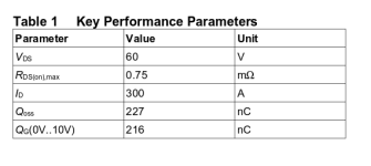
Please considder to implement (after the FOC integration) the new very awesome IPT007N06NATMA1 MOSFET in your next version of VESC. It costs only 1.41 more and is available from 9.12.

Here is comparison with the current MOSFETS IRFS7530TRL7PP

IRFS7530TRL7PP.png
IPT007N06NATMA1.png


Thanks, zener
 
That would be very cool. Is there also a 40V version of these new FETs with possibly even lower resistance?
 
Regarding capacitors:
I haven't really measured and compared different configurations to determine how many capacitors are actually needed, but in general it is better to have more (the downside is that you get a larger spark, but that's what anti-spark switches are for). Having more capacitors will also put less wear on them since the ripple is shared among them and the total ESR gets lower. If you really need to save some space/cents you can try using less capacitance, but I will continue using about the same value.

FOC does not actually output sine waves, it is still switching but it modulates sine waves which together with the motor inductance makes the current more sine wave shaped. How much capacitance is needed to deal with the ripple still depends on how fast switching is done, so high frequency trapezoidal commutation might require less capacitance than low frequency FOC if the difference in frequency is large, even though the modulated current has less ripple with foc. However, in general, FOC will do more switching and require less capacitance. More switching also means more switching losses, which means the the FETs will get warmer when running foc. I have already confirmed that this is the case in my initial tests, which was expected.

Dr_T said:
Thanks for posting that link to SLS Lizard! finally had some time to browse it through. Nothing beats some datas! From what I am trying to understand from FOC so far (which might not be a whole lot yet ), the higher efficiency at partial load, lower ripple / lower stress on batteries and caps is all very welcome for our fast RC car toys :).

@Vedder: you mentioned having more trouble driving a low inductance inrunner (Lizard's 1717?) on FOC than the typical sub 200kv ~12 pole ~60mm outrunners. Is there a way to recognize motors that will work well on FOC, based on their basic properties?

Also, I recently got a ironless 44x85mm 2-pole ~1000kv inrunner I am wanting to try with the VESC; does being ironless make it easier or worse to drive for VESC, or does it not matter at all?

Thanks!

Coreless motors have less inductance in general and are more difficult to use. Also, the coreless motors I have tested tend to be inefficient in general, but maybe that is because of low quality. However, 1000kv and two poles means that the motor has low electrical speed, which is a good thing. You should be able to run that motor at full 12s.

Regarding RC motors and FOC, here a blog post from TI:
https://e2e.ti.com/blogs_/b/motordrivecontrol/archive/2013/11/07/you-will-not-be-able-to-spin-this-motor
They write how their customer has an extremely difficult motor with 9.2µH inductance and that they made it run. Yesterday I measured my 4-pole 2100kv RC inrunner - it has 2µH, which is less than one quarter of that :) It did work with the FOC implementation though, but the estimated current was noisy and off because of the low inductance. I'm surprised that it works. I still need to test this more and under load though, so I will try it on lizards motor some time in the next days.

zener said:
Dear Vedder,

Please considder to implement (after the FOC integration) the new very awesome IPT007N06NATMA1 MOSFET in your next version of VESC. It costs only 1.41 more and is available from 9.12.

Here is comparison with the current MOSFETS IRFS7530TRL7PP
Thanks, zener

Thanks, I will have a look at that. 1mOhm typical and 0.75mOhm is not a huge difference though.

I was hoping to release a beta version of the FOC implementation a bit sooner, but I decided to keep it a bit longer before I release it. The reason is that I want it to work well enough to be useful, and I want to have some auto-detection of motor parameters so that most people can use it without a whole lab to measure their motor parameters. For the sensorless observer it is very important to have correct values of the motor resistance, inductance and flux linkage, and the only parameter that hobby motor manufacturers might specify is the resistance, and it usually is wrong.

As of yesterday I have an automatic estimator of resistance and inductance that works for most of my motors, and the flux linkage estimator is about the same difficulty to use as the old motor detection implementation. I will add that to BLDC tool in the next days, test everything a bit more and hopefully push it to github within a week (I said that two weeks ago as well).

Don't expect any magic from FOC. You will hear a big difference in sound, but you are not likely to gain any noticeable difference in efficiency. The FETs will most likely get warmer and the motor efficiency might increase a bit a low speed, which can be good for hub motors and ebikes. Also, the top speed (or motor kv) will get lower with FOC with a factor of sqrt(3) / 2 or 0.866 since the modulation is a bit limited when full sine waves are modulated. With a three shunt version of the VESC the modulation could be increased to 100%, but that means that the commutation at full speed will be trapezoidal, the same as bldc. Another way to increase the top speed is using field weakening, but I don't know how well that works and how efficient that is on our motors. The difference in sound is really worth FOC for me though :)
 
Thanks for your explanation Benjamin! This stuff is all very interesting, and makes me want to have a better understanding of how it all works.

For anyone interested, Rolf Zimmermann explained the following on RCGroups with respect to motor properties and FOC:
Low R and/or low L are absolutely not a no-go for FOC by principle! It will work well, if PWM frequency can be set high enough (calculating power is needed for this). But higher PWM-frequency will cause more switching losses - therefore max. field-RPM is limited using FOC, if efficiency is focused ...

L is desired - to lower PWM-frequency current ripple in motor phases. Low L can be compensated with higher PWM-frequency. High L will make the motor characteristic less stiff agains higher load (maxRPM will drop with higher load - even R is low).

R is function of wire length (and dia). So R is function of turns. L is function of turns². This is for different number of turns on SAME motor stator.
Different motors (with different geometries and dimensions) will have similar dependences but with other motor-specific constants.

What we found is, there is no general rule for R/L. Most model-motors are at the lower end of R and L spectrum. Industial motors normally have higher L, IMHO due to higher precision in production, allowing smaller gap size in rotor-stator system.

He also said the SLS controllers are limited to about 60k ERPM (he refers to it as field-RPM) as a result of the growing switching losses in the ECU due to higher needed PWM-frequency.

Cool to hear you are implementing R and L estimators in the BLDC tool! Besides being functional for the VESC, it will make it easier for us to compare motors and maybe understand performance differences.

Yeah, I wish my 4485 motor was 12S capable, but it's cheap one out of a 6S RTR car and rotor will probably explode at 40k+ RPM. I'll try it on 8S first to see how it goes. According to spec it's rated 88A... we'll see :).
 
Can anyone advise me? Earlier in the thread it was saying that 12 and anything above 200kv was not working. I've never made a skateboard before, so I would love to know if the numbers that I put in this calculator make sense. The motor I'm thinking of is sk3 6054 260kv and I'm 160 with boots and a backpack.

NyOliver said:
I'm looking for a confirmation that 260kv and 12s work fine. This will be my first build and since I'm going to be in traffic with Manhattan streets I will be happy with a lower top speed. looking for efficiency and smoothness of operation...

Here's the calculator of what I'm about to buy:


Efficiency (%) 70
Battery volts
44.4
Motor RPM
11544
Weighted Motor RPM
8081


Gearing ratio
3.54 : 1
Top Speed Calculations
Top Speed
26.75 mph / 43.05 kph
Weighted Top Speed
18.72 mph / 30.13 kph on 70mm wheels.

The attached image is just a screenshot of the calculator.
 
Dr_T said:
Thanks for your explanation Benjamin! This stuff is all very interesting, and makes me want to have a better understanding of how it all works.

For anyone interested, Rolf Zimmermann explained the following on RCGroups with respect to motor properties and FOC:
Low R and/or low L are absolutely not a no-go for FOC by principle! It will work well, if PWM frequency can be set high enough (calculating power is needed for this). But higher PWM-frequency will cause more switching losses - therefore max. field-RPM is limited using FOC, if efficiency is focused ...

L is desired - to lower PWM-frequency current ripple in motor phases. Low L can be compensated with higher PWM-frequency. High L will make the motor characteristic less stiff agains higher load (maxRPM will drop with higher load - even R is low).

R is function of wire length (and dia). So R is function of turns. L is function of turns². This is for different number of turns on SAME motor stator.
Different motors (with different geometries and dimensions) will have similar dependences but with other motor-specific constants.

What we found is, there is no general rule for R/L. Most model-motors are at the lower end of R and L spectrum. Industial motors normally have higher L, IMHO due to higher precision in production, allowing smaller gap size in rotor-stator system.

He also said the SLS controllers are limited to about 60k ERPM (he refers to it as field-RPM) as a result of the growing switching losses in the ECU due to higher needed PWM-frequency.

Cool to hear you are implementing R and L estimators in the BLDC tool! Besides being functional for the VESC, it will make it easier for us to compare motors and maybe understand performance differences.

Yeah, I wish my 4485 motor was 12S capable, but it's cheap one out of a 6S RTR car and rotor will probably explode at 40k+ RPM. I'll try it on 8S first to see how it goes. According to spec it's rated 88A... we'll see :).

Low R and/or low L are absolutely not a no-go for FOC by principle
Yes, by principle :)

The main problem with low L and high PWM frequency is actually current measurement, especially with two shunts on the low side. The current will be present on the low side shunts only for a fraction of the PWM cycle, especially on high duty cycle, and during this time the shunt amplifiers and filters must have time to settle. It is better with three shunts, but still the amplifiers have to be fast and the switching generates noise.

So R is function of turns. L is function of turns². This is for different number of turns on SAME motor stator.
This is wrong, unless the motor with fewer turns has insufficient copper fill. R is also a function of turns squared since you need thinner wire to fit more turns on the same stator. Therefore, if you double the amount of turns, the wire will be both twice as long and half as thick.
 
Haha, awesome Benjamin, thanks for the correction! :)

What were your thoughts on 3 shunt design VESC again? Is this something you are considering, or is the performance gain not worth the redesign effort?
 
Hi Vedder,

I am using your vesc for the fsi sumo competition in japan (december 13th)

What would cause the VESC to cut the power to the motors if we are seing a PPM signal in the display app config tab but in the real time data tab, the duty cycle is 0. with no fault code.

This happens during quick direction changes, so i'm guessing i'm hitting some sort of limit (most probably a current limit). I've tried raising all the limits (motor and battery) in the BLDC tool, but the problem systematicly reoccurs.

The motors we are using are Turnigy trackstar sensored 1900KV with a 40:1 reduction.

How can we find out what is causing the cutoff, and how can we disable it :)

Thanks!
 
Dr_T said:
Haha, awesome Benjamin, thanks for the correction! :)

What were your thoughts on 3 shunt design VESC again? Is this something you are considering, or is the performance gain not worth the redesign effort?

I think the three shunt design is worth it for difficult motors such as RC motors. The software is really where I spend 95% of the efforts, making new hardware is not too difficult. The three shunt design would be less compact and a bit more expensive though.

blasto said:
Hi Vedder,

I am using your vesc for the fsi sumo competition in japan (december 13th)

What would cause the VESC to cut the power to the motors if we are seing a PPM signal in the display app config tab but in the real time data tab, the duty cycle is 0. with no fault code.

This happens during quick direction changes, so i'm guessing i'm hitting some sort of limit (most probably a current limit). I've tried raising all the limits (motor and battery) in the BLDC tool, but the problem systematicly reoccurs.

The motors we are using are Turnigy trackstar sensored 1900KV with a 40:1 reduction.

How can we find out what is causing the cutoff, and how can we disable it :)

Thanks!

Try to disable safe start in the ppm app. Also, if possible, it would be good if you can use something other than ppm for sumo robots such as uart or can-bus. Then you can get odometry data as well.
 
Can you already give an estimate about what maximum currents we can run later? So far the highest I've seen is 120A or 130A, but I remember you saying with 0.5mOhm shunts and 40V FETs more should be possible. I mean for short durations of maybe 5-6 seconds with average currents much lower, maybe 40-50A on average.
 
Vedder, you rock. Nice job on a slick compact ESC.
 
vedder said:
Try to disable safe start in the ppm app. Also, if possible, it would be good if you can use something other than ppm for sumo robots such as uart or can-bus. Then you can get odometry data as well.


Safe start is disabled, sadly we are running out of time to implement any other method of communication other than PPM. What I find really strange is that we are not getting an error code in the real time data.

We will try tonight to set the "fault timeout" to 0ms... not really a fix, but maybe it's a workaround.

We will also try to ramp up the ppm to the desired value, we're not really keen on this solution because it will add delays to our timing, as you know the japanese robots are extremelly fast. For example, our ppm is being outputted at 200hz. If the current duty cycle is -90% and our desired is +90% and let's say our maximum aloud delays is 25ms. so we would set the duty cycle to -60% 5ms delay, -30% 5ms delay, 0% 5ms delay, +30% 5ms delay, +60% 5ms delay, +90%...

I do agree we are not being very nice with the VESC, hard direction changes under heavy loads can (will) create monstrous current spikes. I just find it strange we are not getting any fault codes.
 
Hi Vedder,

We've done our testing, we needed a 250ms ramp time for the motors to stop stopping, this is really not optimal. So this tells us by adding a software "low pass filter", it fixes our problem.

Would you recommend adding flyback diodes on the FETS?

Also, if all else fails, would you be open to a live debugging session?

Thanks
 
Hey guys,

I have a question regarding the maximal Lipo to VESC wire length.
I am asking because I had the idea to build a Lipo backpack which can be used for an eSkateboard and also with an eBike.
So you can easily switch between them and don't have trouble with the big (12s/10.000mAh) Lipo under your skateboard.

I know that one should make the Lipo to VESC and also VESC to Motor wire as short as possible, but hope with a big enough decoupling capacitor (is the Vedder anti-spark-unit with a lot of capacitors a step in the right way?) it will maybe work. I don't find others using a Lipo backpack, so there should be a reason. :?
Maybe someone has an idea or had seen someone using a backpack.

Regards
 
Back
Top