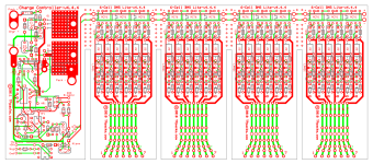
12s2p LiPo pack kit including 12-channel BMS "Lite" Board

Pure said:
I was just thinking.. As much as I would trust any BMS you put out over anything else readily available. Knowing the nature of Lipo, I would want either extra plugs on the board (prob too hard) or special balance cables to allow us to tie in CellLogs into the pack for active, permanent monitoring. Maybe you can offer the extra paralleling cables as an upgrade for extra $?

If you look, you will see an 18-pin VAL-U-LOK connector on the right that brings out all of the cell connections. This could certainly be used with a couple of CellLogs, or it can be used with the same Hyperion 12s harness plug I've been offering for use with the 14-channel Hyperion 1420i balancing charger.

-- Gary
 
Hi Guys,

This may sound like a stupid question, but does this bms do both hvc and lvc ?

Also what is the max charge and discharge rate of the bms?

I would also like a 16S bms Gary if you could build them you would sell many indeed! I currently have 2x 6S + 1x 4S to make 16S and 2P for 10ah. The option to make 20ah would be teriffic too!


Mark
 
Ahah! I didn't even think of that.

Sweet!
 
o00scorpion00o said:
Hi Guys,

This may sound like a stupid question, but does this bms do both hvc and lvc ?

Yes, it works just like the Zephyr BMS, and has a functionally identical charge control section. For LVC, there are connections for the throttle signal and controller so that if a cell's LVC circuit is tripped, it will briefly pull down the throttle signal. During charging, the HVC signals are used to control the charge current so that no one cell can go over the HVC limit, which is about 4.16V.

o00scorpion00o said:
Also what is the max charge and discharge rate of the bms?

There's no max discharge rate at all, since we use the throttle pull-down technique to control the load. Unlike the bulk of the "commercial" BMS boards, there's no discharge FETs that limit the discharge current. On the charge side, with a single 100V FET, the charge current limit will be about 20A.

o00scorpion00o said:
I would also like a 16S bms Gary if you could build them you would sell many indeed! I currently have 2x 6S + 1x 4S to make 16S and 2P for 10ah. The option to make 20ah would be teriffic too!

Like I said, this is down the road. I'm only going to do one of these that will come pre-assembled/tested, for now. By far, I think 12s2p is the most common setup, and two can be used for a 24s2p configuration as well.

-- Gary
 
Hi Gary,

Thanks for the reply.

No discharge limit is very good indeed!

I will look forward to seeing 16S in the future. :)


Mark
 
Here is a 4 x 6 BMS Lite layout that I will do as well. This can be a replacement for the LVC-only and LVC-HVC LiPo boards that I have been doing, as it can do these functions, or the whole BMS function, depending on what parts are installed. As with the previous "tearoff" LVC/LVC-HVC boards these can be left connected, or they can be split into separate boards. The section on the left is the same full Zephyr charge control section, with the auto-turnon and adjustable EOC shutdown functions.

4x6-channel BMS Lite-v4.4.3x.png

Initially, I'll just offer this like the full Zephyr BMS, as a PCB with a BOM and a detailed set of instructions, but at about half the price. If the demand is there, I might also do a version with three 8s sections. Anyway, these can used for "custom" setups, but for the pre-assembled kit version, it will be specific to 12s2p, for now.

-- Gary
 
Update...

I've been getting more than a couple PMs about pre-orders and questions of availability. As I said previously, I will post that info in this thread, at the appropriate time.

I've had to make a few tweaks to the cell circuits, to adjust the shunt current and the HVC trip point. I found that with the initial values I had been using, the HVC was tripping a bit too low, like about 90mA. This is too low. After doing some tests, I found that the shunt current can be as high as 130mA and nothing even gets warm. You start to feel the heat at about 140-150mA. Another problem with the low HVC trip point is that the inexpensive red LEDs I'm using don't come on until the shunt current is about 100-110mA. Anyway, I raised the HVC trip point to just over 130mA, and everything works well. Anyway, I'm just now getting ready to assemble the first pack. After that, and I see what other layout tweaks might be required, I'll get a new run of boards done.

-- Gary
 
gensem said:
Gary, would you consider making thoses in a shape to fit 12s 2p 8000mah Zips?


BR

Actually, I think the board would work fine. I'll have to check the length, though. These use the 5.5mm bullets, so I'll need two larger adapters, and the end plates would be a bit bigger. But the answer is yes, I will consider supporting these packs. 8Ah is huge. a 12s2p pack is 16Ah. I like this a lot. :)

I'm updating this to use the resistor arrays and quad versions of the opto chip. This cuts the parts count way down, and makes it a whole lot easier/faster to build.

-- Gary
 
Gary you are awesome!! Im thinking about an HS with 12s lipo :)
Let me know when you have the final design ready so I can get the lite bms, meanwell and hyperion from you. Zips ll probably come from HK.

Btw if I got it right the 4 x 6 lite board would need 2 hyperion chargers for 24s 2p?

Thanks
 
Does it??? LOL
I tought it was lite because it did only lvc and no balacing.
So I need only a 50v powersupply for charging?


o00scorpion00o said:
Forgive my dumbness, but why would you need the Hyperion if this does all the balancing?


Mark
 
GGoodrum said:
Finally, there's a single 18-pin VAL-U-LOK connector that is wired just like the 12s charge plug used with the Hyperion 1420i RC-type charger. This plug can be used to check individual cell voltages periodically, just to make sure no cells are starting to go hinky.

...
-- Gary

I think you don't need the balance charger, but I'm not sure! :mrgreen:

- Fabio
 
gensem said:
Does it??? LOL
I tought it was lite because it did only lvc and no balacing.
So I need only a 50v powersupply for charging?


o00scorpion00o said:
Forgive my dumbness, but why would you need the Hyperion if this does all the balancing?


Mark

That's right, this does the balancing so all you need is a current-limited supply that can be set at 50V. The only reason for the Hyperion-compatible connector on the end is to provide access to each cell, to test for health, etc. This can be done with a DVM, one cell at a time, with one, or more CellLog units, or all at once with something like the Hyperion.

-- Gary
 
It's really exciting stuff Garry well done mate! :D

And the best part of it all is the fact this bms is far less complicated than some of the very expensive bms's out there that have been very well known to fail!

And I love the fact there is no discharge limit and the fact that when the cells go low it doesn't kill all the power just throttles back, it's really wonderful stuff, it's what LiPo users have been waiting for!

You say Garry that 2 of these packs can be connected in series for 24S, would you series it at the output of the bms? and would there be any additional electronics involved?

I think you deserve An award from Endless Sphere Garry! :mrgreen:

I can't wait to see pics of packs up and running!

Mark
 
so for the 4 x 6s lite bms we ll only need a 100v power supply (im assuming 4.15 cell hvc)?
 
Gary,

You'll probably answer this question at some point with a picture, but I'm curious now... Are the batteries to be placed on top of the pcb, between the two end caps? On top of the resistors? If so, that would seem to be a bad idea. So, either my understanding is flawed or you have a reason for this design.

I would think that the pcb should be on top of the batteries. Maybe that's the way its intended? :?
 
number1cruncher said:
Gary,

You'll probably answer this question at some point with a picture, but I'm curious now... Are the batteries to be placed on top of the pcb, between the two end caps? On top of the resistors? If so, that would seem to be a bad idea. So, either my understanding is flawed or you have a reason for this design.

I would think that the pcb should be on top of the batteries. Maybe that's the way its intended? :?

Yes, the packs go above the pcb, but not directly touching. There's a gap of about 3/8". With this design, though, nothing gets hot at all, not even a little. The max current the shunts pass is around 120-130mA and nothing gets even warm to the touch until the current goes above about 150mA.

You will be able to put two of these in series, for a 24s2p setup. You just need to also put the charger connections in series, if you are using a single 100V charger/supply setup. You could also charge each 12s2p pack with separate supplies/chargers, as long as they are isolated.

-- Gary
 
Would it be possible to use this with 5s packs instead, or can it only be a 12s 2p configuration. For my setup I would need 20s2p so 2 5s2p in series would work. 24s2p is to much for my controller.
 
I have some ping 16s chargers(60v) that I can mod to output 50v, will I ll be able to use it without problem?
 
nomad85 said:
Would it be possible to use this with 5s packs instead, or can it only be a 12s 2p configuration. For my setup I would need 20s2p so 2 5s2p in series would work. 24s2p is to much for my controller.

Yes, you could do two 10s2p setups by not populating two of the channels and by using 6-pin JST-XH connectors instead of the normal 7-pin variants.

gensem said:
I have some ping 16s chargers(60v) that I can mod to output 50v, will I ll be able to use it without problem?

Yes, these should be fine. Ideally, you'll want to set the voltage between 49.5-50.0V. The procedure will be to adjust the voltage so that the red LEDs come on, and then back off just a little from that. This will set the CV point of the charger right at the point the shunt circuits come on. With a perfectly balanced pack, the shunts (and LEDs...) won't come on at all. In reality, packs are never perfectly balanced so what will happen is the high cells will have its shunts come on, so that current can be bypassed to the cells that need to catch up. Once the low cells do catch up, the LEDs will go off as the shunts shut down, and the charge current will drop down close to zero.

-- Gary
 
If you were to run these as 30 or 36S, you would need a higher voltage mosfet for the charging section correct?
 
heathyoung said:
If you were to run these as 30 or 36S, you would need a higher voltage mosfet for the charging section correct?

Yes, that's right. The ones I'm using are good for 24s/100V. A 4115, for instance, I believe is good to about 150V.

-- Gary
 
I don't know all the costs just yet, so for those PM'ing me for that info, I'm sorry, but I hope to figure that out soon. I'll post the info here.

We've been doing two parallel efforts, this 12s2p "Lite" variant, and the version that is CellLog-based. The boards for the CellLog version were submitted Friday, and I will get them tomorrow. In the meantime, Richard and I have been working on the this "standalone" Lite variant. Mainly what we are changing, for both versions, is the charge controller section. Based on the issues we've seen with the full Zephyr BMS controller, we wanted to simplify things for both this version and for the CellLog variant. With the Zephyr charge controller, there was an auto-shutoff function that monitored the charge current, and shut off the charge current, and the main LED, when the current dropped below a preset level. For the Lite variants, what will happen is that the LED will stay on, and be solid green at the end of the charge process. If the individual red shunt LEDs are off, and the LED is green, the charge process is complete. Unplugging the charger/supply, at that point, resets the circuit and the LED stays off until the next time the charger supply is connected. During the CC charge phase, the main LED will be orange. If there is an imbalance, the shunts for the high cells will come on, along with their respective LEDs. Once the main LED is green and all the shunt LEDs are off, the pack is fully charged and balanced.

Anyway, today I'm hoping to finish the layout changes for the basic 12s2p version. Initially, at least, I'm probably just going to do this one, plus a slightly larger version that will work with the Zippy 6s-8000 packs. I like these a lot because one 12s2p setup of these has more capacity than a 12s3p configuration of 5Ah packs. :)

-- Gary
 
Back
Top