12s2p LiPo pack kit including 12-channel BMS "Lite" Board

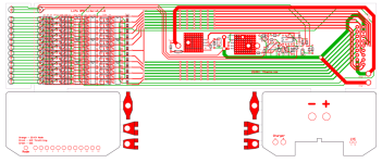
After thinking more about the layout, I decided to split the functions, and put the LVC circuits down on the board that gets embedded with the pack. That way, the "box" doesn't have to be connected during discharge. The box then becomes a simple "CMS"/auto-balancer that plugs into the pack for charging, with the single 18-pin plug. It can also be left connected, if that is desirable, all the time. The charge control logic isn't enabled until the charger/supply is plugged in.

Here's what the latest PCB looks like:


More later...

-- Gary
 
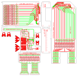
This, I believe, will be the "final" version. In addition to the long LVC/parallel adapter board, for the horizontally oriented shrink wrapped packs, I've added a new dual LVC/6s4p parallel adapter that can be used with any pack configuration.

2x6s-channel BMS Lite-v4.4.5h.png

The "boxed" portion, which has the balance circuits and the charge controller section, can work with either LVC setup, and can eithr be left connected, or just used as an external balancer and charge controller. All that is needed is a "dumb" CC/CV charger or a simple current limited 48V supply, like a MeanWell. The logic to turn this into a "smart" charging setup is in the charge controller, with its HVC interaction.

We should be able to start offering these starting late next week. There will be options for one or the other, LVC board solutions, or just the balancer/charge controller by itself for use with existing setups. This is plug-compatible with the Hyperion 12s charge harness.

-- Gary
 
Fishmasterdan said:
Gary;
Do you think this will be ready anytime in the near future? I really like the original concept!!

The boards for the version shown above will be here this afternoon. I will build up one complete set and do some tests. After I get this going, I'll go back to looking at the original layout, with everything on one board, if there is enough interest. Like I sad before, I need to do something to shield the heat from the shunt circuits, so that the cells don't get warm. The only other issue for this original approach is that it is pretty much specific to the horizontally oriented 12s2p configuration that uses four 6s5000 Zippy/Turnigy packs. A separate board would be needed for 12s2p packs made from the 8Ah Zippys, because they are longer.

The scheme shown above supports both 12s2p shrink-wrapped setups using either the standard 5Ah pack, or the larger 8Ah versions. It will also support setups that orient the packs vertically, and in larger capacity configurations, like 3p, 4p, or even more.

I should be able to start posting some pics tomorrow.

-- Gary
 
Honestly as convenient as the original setup would be, a one size fits all model is probably the best from a cost and production over head point of view. If you're only producing one model it will obviously allow you to focus on that one and deliver a better product.

Either that or I have no idea what I'm talking about :oops:
 
Cool. The pictures are boken, but very cool.
 
LoL Arlo...

But anyway, the split design makes more sense for me too, even tho Im really after Garys cell-log board.
 
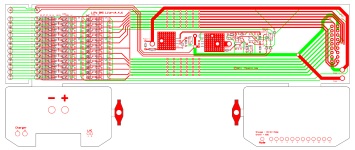
Okay, I ran into a couple of layout issues with the "boxed" approach, which can be fixed in the "production" version. The good news is that the circuits work as advertised, which is not really a surprise because they have been tested many times now, but this at least verifies that I didn't screw up anything in this version. :roll: :) The only issues with this one now are having a couple of parts too close to the box rails. I'm fixing these on my test unit, so I will still be doing some more testing, etc.

While I was making the layout corrections, I went ahead and also did a new version of the original single board concept. In this version, I made it so that it will also work with the longer 8Ah Zippys.

12-Channel BMS Lite-v4.4.5d.png

I did this by adding some extra parallel connectors, and by adding a second set of LED mounting holes. If this is to use the 5Ah packs, the extra section at the left end of the board is simply cutoff. I also have a new assembly scheme that adds a heat shield, to protect the cells from the shunt circuits. Hard to describe, but it is really pretty simple.

-- Gary
 
for me I like the idea of a plug and play option for the kids. I am always paranoid letting them use my lipo's. So I would love any one of the plug and play options.
 
GGoodrum said:
Okay, I ran into a couple of layout issues with the "boxed" approach, which can be fixed in the "production" version. The good news is that the circuits work as advertised, which is not really a surprise because they have been tested many times now, but this at least verifies that I didn't screw up anything in this version. :roll: :) The only issues with this one now are having a couple of parts too close to the box rails. I'm fixing these on my test unit, so I will still be doing some more testing, etc.

While I was making the layout corrections, I went ahead and also did a new version of the original single board concept. In this version, I made it so that it will also work with the longer 8Ah Zippys.


I did this by adding some extra parallel connectors, and by adding a second set of LED mounting holes. If this is to use the 5Ah packs, the extra section at the left end of the board is simply cutoff. I also have a new assembly scheme that adds a heat shield, to protect the cells from the shunt circuits. Hard to describe, but it is really pretty simple.

-- Gary

I hope you can get this board in to production soon. My money is waiting :)
 
VoKuS said:
I hope you can get this board in to production soon. My money is waiting :)

Getting closer, actually. :) I've got it down to two variants now, the shrink-wrapped, all-in-one standalone version, shown above, and a new variant, shown below, that will work with, or without two CellLog units. This will support three types of setups, a full CellLog-based 12s BMS, where the CellLog units provide the LVC and HVC signals for each of the 12 channels; a "hybrid" variant, of sorts, where the packs have an embedded LVC/parallel adapter board that handles the LVC function and the CellLog-based unit is used as a "CMS" to control the charge process and balance the cells; and finally a standalone version that doesn't use the CellLogs. The latter variant is functionally identical to the 12s2p shrink-wrapped version shown above, but will work with virtually any pack size/orientation.

2x6s CellLog BMS Lite-v4.4.7.png

Testing continues on the standalone version, mainly tweaking the HVC trip point setting. With the CellLog-based versions, the HVC setting is completely adjustable, so it can be fine-tuned to a particular setup and charge rate.

The boards above have been ordered, so I will test one of these later this week.

-- Gary
 
Getting exciting. Um, what is cell log? Is this one of your products or a generic term for some sort of charge controller? I'm new to the battery side of EV tech so apologies if I should know...
 
modern_messiah said:
Getting exciting. Um, what is cell log? Is this one of your products or a generic term for some sort of charge controller? I'm new to the battery side of EV tech so apologies if I should know...

A CellLog is a handy little widget that accurately monitors up to 8 cells in a battery pack and has various display readouts for showing the information on each cell. It also has various alarms that can be set, such as individual cell low voltage and high voltage trip points, overall pack limits and allowable deltas between low and high cells. There are two CellLog versions, one that adds a logging/recording function: http://www.progressiverc.com/celllog-8s.html

The only thing that keeps these units from having all the functionality of a full BMS is a way to balance the cells. We can add this capability by adding the shunt circuits. In the CellLog-based variants of the this new 12s solution, we add 12 shunt circuits, plus some logic to isolate the Alarm outputs from both CellLog units, so that they can be used to trip the LVC and HVC circuits.

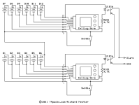
CellLog BMS Lite HVC-LVC Circuits-v4.4.7.png

The switch enables the CellLogs and the optoisolator chip is used to isolate the Alarm outputs. The CellLogs will sit on top of the box, using the custom lid provided, similar to the older version, shown below:


I'll have some pics of the actual unit later this week. Anyway, the idea is that the CellLog units can provide the LVC and/or HVC signals, and then also provide readouts of each individual cell's voltage, and with the "S" version, record/log the data. For my own setups, I plan on using these mainly as a "Charger Management System", or CMS, that is only plugged into the pack to charge and balance the packs. All of my current LiPo setups are either 12s2p or 12s3p configurations, all with embedded LVC/parallel adapter boards. I have two 12s3p 15Ah packs on my Townie, two 12s2p 10Ah packs on my wife's Townie and one each 12s2p 10Ah packs on my two folding bikes. All of these have the 12s single plug harnesses that are compatible with the Hyperion 12-channel harness I've been providing. This new box has a matching connector with the same pinout. I plan on using two of these units, each with two CellLogs, with all of my packs.

-- Gary
 
Hi Gary,

Forgive me if this sounds dumb!

From what I gather from all this is that you can program the hvc/lvs yourself to say 3.5-4.2/3.0-4.0 if you want to extend life or max capacity, is that correct? and the alarm of the cell log will shut off supply under lvc and the cell log decides when the hvc will trip while charging?

And what about the throttle lvc, where does that come into it?

Mark
 
The short answer is yes, both the LVC and HVC trip points can be set, if the CellLogs are used. Having a settable LVC point, is not all that important, in my opinion, due to the nature of how LiPo cells behave. With SLAs, for instance, a full battery starts out at around 14V, and is down to about 10V when it is fully discharged. When it is half-full, the voltage is at 12V, which is why they are "nominally" rated as 12V batteries.Lithium cells, and LiPos in particular, don't have this linear voltage drop, from full to discharged. Most newer LiPos will drop pretty quick from whatever they are charged to (i.e. -- 4.15V...), to their "nominal voltage of 3.7-3.8V. They will stay pretty close to this until the end of capacity, when the voltage will drop to zero very quickly. If this happens under load, the cells can actually kill themselves, by going to cell reversal. You can easily have a case where the "resting" voltage is still up around the nominal point, but they could be right at the edge of the discharge "cliff" where the next load put on the pack will cause these cells to "jump" and quickly drop to 0V. the whole purpose of cell-level LVC is to catch these cliff divers, in time to prevent the voltage from going too low. From my experience, it doesn't much matter if this is 3.0V, 3.3V, 2.7V, whatever. The resting voltage will still always be close to the nominal point. There just won't be any more "gas" in the tank. Now, if instead of happening under typical ebike loads, the pack is drained down slowly, like if something is left on for an extended period, the cell voltages will drop a bit more slowly, as the capacity reaches empty, so you might see a resting voltage of 3.5V, or 3.3V, but for when you are actually using the bike, if an LVC circuit trips, and the load is cut, the resting voltage will be much higher than that, like around 3.7V still.

With the CellLog versions of this unit, a small relay is used for the LVC output. This relay has two sets of normally open and normally closed connections. This relay is way too small to be used to cut the discharge current directly, but it can be used in a number of ways. It could, for instance, still pull down the throttle signal, or activate a controller's ebrake input, or the throttle signal wire could be routed through a set of the normally closed contacts, so that when an LVC trip occurs, the throttle signal is interrupted. You could also use a set of the contacts to drive a buzzer/alarm, or maybe a large contactor that cuts the discharge power. I'm really not a fan of this approach because it can't be good for any controller to be cycling main power to it. :) Cutting the throttle is still the most effective way I know of to cut the load on the battery, to keep the cliff divers at bay.

Having an adjustable HCV is going to be a lot more useful, in my opinion, but not for the obvious reasons. The adjustability will be useful to tailor to specific charge setups, more specifically to max charge currets. The way this will work is that shunt trip points are fixed. This is adjustable at the time of build, by changing the divider resistor values, but with the values I'm using now, the shunts first start coming on around 4.14V. What you do is set the "charge to" voltage a bit higher than this, around 4.15-4.16V per cell, so for a 12s pack, it would be 49.8-49.9V. With a reasonably balanced pack, all the cell voltages will get to the point the shunts (and red LEDs...) come on within seconds of each other. For packs that are a bit more out-of-balance, it might take a bit longer for all of the shunts/LEDs to come on, but usually no more that a minute, or so. Anyway, when the cells are all at that point, the main LED will turn green and the charge current will be cut. The shunt circuits will then bleed off all the cells to the point the red LEDs go off, and at that point the cells are fully charged and balanced.

-- Gary
 
Using a pre-charge resistor that's separately wired from the LVC main power circuit by having the caps charged, will it still stress the controller by the rapid power cycle?

GGoodrum said:
You could also use a set of the contacts to drive a buzzer/alarm, or maybe a large contactor that cuts the discharge power. I'm really not a fan of this approach because it can't be good for any controller to be cycling main power to it. :) Cutting the throttle is still the most effective way I know of to cut the load on the battery, to keep the cliff divers at bay.
-- Gary
 
Gary,

Thanks for taking the time to write such a long reply, I appreciate it!

So basically, there will be a version of this bms without the cell-log with fixed (by you) lvc/hvc values? 4.15 charge and as for lvc, are you still going to use throttle lvc? I think once I've got this in my head I'll be fine! :shock:

Also what kind of charger would be acceptable to use with this bms, any cc/cv such as a ping type charger, or might you offer chargers too because I find that trying to adjust these chargers can be a bit daunting especially since there is no output without battery connection, and it's too easy to mess up the settings!


Mark
 
o00scorpion00o said:
Gary,

Thanks for taking the time to write such a long reply, I appreciate it!

So basically, there will be a version of this bms without the cell-log with fixed (by you) lvc/hvc values? 4.15 charge and as for lvc, are you still going to use throttle lvc? I think once I've got this in my head I'll be fine! :shock:

Yes, that is correct, there will be a version that doesn't require the CellLogs, and yes, the throttle LVC will still be used. I have yet to find a better way to kill the load on the cells. It is elegantly simple and extremely reliable. I will do the same thing with the CellLog version.

o00scorpion00o said:
Also what kind of charger would be acceptable to use with this bms, any cc/cv such as a ping type charger, or might you offer chargers too because I find that trying to adjust these chargers can be a bit daunting especially since there is no output without battery connection, and it's too easy to mess up the settings!

All that is needed is a "dumb" CC/CV charger, like a Ping, or any 48V power supply that has current limiting. The Meanwell-type supplies, like the S-350 series, will work, but they need the "R33" mod to bring the max current down to the rated level. These supplies are typically used as supplies in things like sound amplifiers, which don't have continuous loads like a charger. Because of this, they set the current limit to about 130% of the rated max of the supply. That way the average current used stays under the rating. If we want to use one of these as a battery charger, the current limit needs to be dropped down to the 100% level. That's what the R33 mod does.

There are lots of other 48V supplies out there that don't need any sort of mod. A lot of the older telephone switching systems used 48V supplies so there's lots of surplus units on eBay all the time, both new and used. Anyway, if I can find a source of a decent 48V CC/CV supply/charger I might buy a quantity and make them available as well, or at least point people to where to get them. :)

-- Gary
 
That's great Gary thanks, I think I got it now, this is really interesting stuff indeed!

please make a 16 or 18S you know you want to! :twisted:


Mark
 
Okay, we are getting closer. :) We made a slight change to the HVC control philosophy, which improves a number of things. Previously we had the HVC opto outputs in series, and then used this signal to trip the EOC shutdown logic. The idea being that once all the shunts were fully on, the cells were all full so the charge current could be shut off. This works quite well, but it means that until the last cell's shunt comes on, the rest of them are cooking away because they are saturated. To prevent for the case where you have one weak/bad cell from running away in an overvoltage condition, we used the CellLog's HVC signal, but set higher, like around 4.20-4.25V. If a cell tripped this limit the EOC shutdown would also be engaged.

The next change was to add this secondary HVC signal to the standalone variants as well, so there'd be the same sort of errant cell protection. What we did was to implement two HVC signals, one a bit higher than the other. The lower one drives a series string of optos, which means for the signal to go active all of these lower HVC signals need to be on. The second, higher HVC set of signals drive a "standard" parallel string of optos, so this HVC signal will trip if any of these higher HVC signals trip. In the charge control logic, we still use the ALL HVC line to trip the EOC shutdown, but with this latest version we will now use the ANY HVC to do the same sort of power cycling/throttling we've done in the past. This will still keep the errant cells from going too high, but it also means the shunts that come on first won't go into a swamped/overload condition, so they will run much cooler. This is particularly important for the 12s2p "shrink wrapped" version.

All-in-all, this is a much better control scheme, as it can be used with a wider variety of charge setups. There's a few more parts, but well worth the extra time and effort, in my opinion. :)

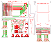
I ordered some of both of these PCBs this morning:
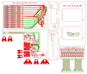
2x6s CellLog BMS Lite-v4.4.8.png

12-Channel BMS Lite-v4.4.8.png


The first one is for the "boxed" version, which uses the embedded LVC/parallel adapter boards. The standalone (i.e. -- non-CellLog...) version contains the shunt circuits, including both ANY HVC and ALL HVC signals, plus the new charge controller. This box can either be used as a "CMS", and only connected via the single 18-pin charge plug, during the charge process, or it can be left permanently connected to the pack. There's no drain on the cells because the charge control logic, including the main LED, is off until the charger/supply is connected. If CellLogs are to be utilized, the box can be used as a CellLog-based CMS unit and the CellLogs can be used to generate the ANY HVC signal. For this case, the custom lid is used, which also includes the CellLog alarm signal isolation circuits.

The second PCB is the updated 12s2p shrink wrapped "kit" version. This variant is functionally identical to the boxed version, plus the LVC/parallel adapter board, but contains everything on one board that runs along the bottom of the 12s2p pack. Special end plates are provided to stick on the ends of the pack, prior to shrink-wrapping the whole assembly. This variant can use either 6s-5000, 6s-5800 or 6s-8000 Turnigy/Zippy packs.

I will get these boards on Thursday, and will spend the weekend doing verification tests, to make sure I didn't screw anything up and that everything works right. Assuming that effort is successful, I'm hoping we will be able to start making both of these variants available starting next week sometime. :)

-- Gary
 
Gary, im really really looking forward for this and the 3x8 channels cell-log variation.
I already have alot of 8000mah zippys waiting.


BR
 
Back
Top