• Hello ES! We could use some help to get us past the finish line on building the new knowledgebase for the forum.
    Can you donate? Please see our fundraising page. Thank you!

2008 CRF250R - QS138v3 70H - ANT - Sanyo UR18650-RX 20s20p - Votol EM260

Shock has been serviced and is back on the bike. It's a Frankenstein made from two shocks I gave out for service. I've put the 450cc spring on it which should be about for a 85-95kg rider. I'm lighter but was feeling the rear too soft and the bike constantly felt unbalanced, also partially because of the stiffer front. Now the rear is indeed quite stiff, but the overall balance seems better.

IMG_20250921_171655.jpg

I've also put handlebar extenders on to see how I like the bars being a bit more to the front. They're a bit too long at 55mm, but that's much cheaper than finding a new triple clamp with adjustable clamp locations, though that would be ideal. The current location feels good for standing, there's a lot of space, but the steering feels weird and the increased leverage made it twitchy. Maybe some of that could be remedied by more steering head preload.

IMG_20250921_180521.jpg
 
Did a small test ride - amazing how much change can be felt from a spring stiffer just by one "size". It definitely sits higher now, definitely puts more weight on the front, which is also helped by the new handlebar location. The handlebar feels weird at slow speeds but it's kinda okay when riding; I think a compromise +30mm location would be ideal; I'll make a set in CAD and get them made, that's still much cheaper than a new triple clamp with offset locations.

Overall the bike feels about even and balanced between front and back now. I did effectively all easy possible changes to make the front softer and the rear firmer and higher, and they all compound together. While I'm glad that I got to this point, I feel that the next step would be to make the front even softer - get 3.8N/mm front springs (or ideally even softer, maybe 3.6, but those are very rare in this size), get softer cartridge springs in (already arrived from the US), and maybe work on the valving even more. The current setup would work great on an MX track, but since I use the bike mostly in enduro, I feel it might be a tad stiff.

1758723687327.png
Ironically, I'd love to swap the suspension between my rally KTM and the CRF right now. The KTM is exactly plush and comfy for woods riding, but I'm starting to push its limits when I go faster in races. I already run settings at or past "sport" there. The CRF's suspension is definitely a different beast, I wouldn't say it's particularly worse (even though it's 15 years older) but the entire chassis definitely was built with another purpose in mind.
 
Last edited:
Yesterday I had my first breakdown failure that required a tow home (fortunately, not very far). I was out riding during the weekend, and was doing the usual - mix of fast and technical enduro, some sand riding etc. In a middle of a not particularly steep but quite loose hill climb, my power suddenly cut out. I had similar things happen before, very briefly and intermittently, but a reset always fixed them. Well, not this time. I pushed myself to the top, pressed all the buttons, nothing. Took the phone out, BMS is reporting 10V on cell 19 and 5.5V on cell 20.

Uh oh.

It did also say "severed series connection" though, which i understood as "one of the balance wires broke". I tried to override it in the menu, but no high-level passwords worked and there didn't seem any way to bypass it. The battery was perfectly fine, but the BMS couldn't see that, so he cut the power. I guess, fair, but I'd love to be able to bypass the protection in such a case and treat it as a warning rather than an error.

Back home, we disassembled the pack, which required unglueing the lid. This was mildly annoying but doable with some prying and some knife work. At the very least it confirmed that my choice of polymer adhesive sealer was spot on; it's flexible and sticky enough to keep everything tightly sealed and firmly attached, but soft enough to open out in case the battery needs service.

I didn't take many pics of the repair, my assistant did and I might get them later, since i was fixed on the repair, but the cause of the problem was that the balance wire was attached to a nickel strip that bent over the corner of the battery. This corner, together with the other wires, was rubbing on the enclosure, ripped through the layer of tape I put there for protection, and broke off. We routed the cable through the cell spaces and soldered it to a cell terminal strip directly. Hopefully the other tabs will stay attached for a while longer - I'd love to get rid of this battery (likely together with the rest of the bike minus my suspension) and build a new build with a new battery, likely larger.

The battery ran fine after the fix, although it's only held close by duct tape right now.
 
This happened to me once as well (loose balance connector), and it's a scary thing to open your BMS app and see a cell voltage reading 10V. Obviously an error, but when you see it in the heat of the moment, you're sure the pack is about to catch fire
 
Yeah, my first instinct was "oh shit" especially when it happened when i was pulling max power (around 20kW at the time). But once I looked at the temps which were all below 30C and saw the warning text I figured that would totally fit something silly like that. I had the advantage of seeing this before because two wires were broken when i received the package with the battery internals.

Edit: Oh, and I completely forgot to mention, I finally got my "bike programming laptop" and took it with me. Just before the trip, i disabled soft start on the regular mode. This made it absolutely miles ahead better in lifting the front, but suddenly i wasn't getting any traction. All the nice crawl-ability i had mostly disappeared.

As a fix, I tried a different approach. Instead of turning the slow start back again, I reduced the power on both modes, to 120A on regular and either 150 or 200A in sport (can't remember now). This still kept the bike quick to accelerate and much more responsive, but dialed the torque back to reasonable levels. What I really need is a phase-current-per-level or even more complex torque curves, but I know that I won't get this with this controller. It's really a freaking shame they won't just release the firmware source code. We'd have a custom build and a full ecosystem of tunes, tools and tutorials in a matter of days, probably tripling their sales... For now, I guess I'll just plan the next build with a 96V fardriver.
 
Last edited:
I decided to tackle the traction issues:

wheel.jpg

The same shop that I got the front wheel from suddenly had the 18" rear in stock. Score! Later on I've realized that this particular wheelset was put in Chinese Barton NXT300. They copied the CRF's dimensions 1:1, but laced 18" rear by default, which I'm very happy about. The wheels are dirt cheap and the front has been holding up fine, so I decided to give the rear a try. I wanted more rubber for more grip, softer compound for more stickiness and more balloon to absorb hits (I'm sure @neptronix will love this sizing). This is a 120/100-18, which comes out slightly larger than my 110/100-19 in overall dimensions, but with radically different rubber-to-rim ratio. I checked with my spare swingarm and it should fit just fine. It's a MH tyre (medium-hard surfaces) but with soft rubber and light carcass, so it should be perfect for the local singletracks with a lot of roots, as well as climbs over leaves and the like.

Weight wise the entire wheel is 10.5kg, the tyre is about 5.6, the wheel about 4kg. The entire tubliss system is surprisingly heavy and it might save weight but only compared to an UHD 4mm+ tube.

I decided to take another experiment and put a Tubliss inside. I actually did that on a live stream, but I talked in Polish, so probably not as interesting for most folks here. Long story short, it took me about 1h40m to get the tubliss on the rim with prep, about 10 minutes to mount the tyre and about 5 to pump everything together and do a check. I assembled it dry and predictably it started to leak, so I just added some latex sealant. After 5 minutes it seemed fine, so I left it overnight. In the morning didn't seem to lose any pressure, so I'm calling it good. I plan to start using it at about 0.8 bar (11 psi) which is at the upper end of the recommended pressures, and see at which point I'll start to notice problems in cornering.

Now fingers crossed for chain clearance :)
 
In the tubeliss instructions I have it says that you should spray on lots of soapwater between the tire and rim before pumping air in it.
That is what I have done, it has never leaked for me. Well, it has leaked several times, but trough the tire every time.
Nice with new wheels, your old ones didn't seem great ;)
Hope the quality is decent, but I guess time will tell.
 
In the tubeliss instructions I have it says that you should spray on lots of soapwater between the tire and rim before pumping air in it.
That is what I have done, it has never leaked for me. Well, it has leaked several times, but trough the tire every time.
Nice with new wheels, your old ones didn't seem great ;)
Hope the quality is decent, but I guess time will tell.
Tubliss has an alternate set of instructions if you plan to use sealant. In that case, you don't use soapy water as that apparently causes problems for the sealant. Instead, the sealant is spread over sealing surfaces and added into the tyre just like with MTB. I did that after initial leak was discovered and it seems solid since.

As for the wheels, I know it's a gamble; worst case if they start bending I'll just reuse the hubs (which are pretty nice) and relace real rims on them, but so far the front has shown no signs of problems.
 
Unless you plan on riding fast paced enduro or MX don't bother at 0.8bar, got for 0.6 and below. If you low hill climbs, getting stuck and all that good stuff you will love tubliss. On my 125exc I ride with 3psi of pressure, grip for days !
 
I ended up going down to about 0.5-0.6 and the traction is indeed fantastic. The added rubber also massively improves suspension performance.

In the 2nd ride of this season, I had a very nasty accident. We ride a lot through the trees, and there's a lot of loose branches. As you know, I still use a cable throttle. So, what I think happened, on a downhill a branch snatched on my cable and pulled it out of the housing. I closed it on the bar but the cable was still pulled (and i only have one cable, not two), which launched me up in the air and back. I fell on my butt, the bike fell on its tail and collapsed to the side on my foot.

I managed to get the mudguard back (not broken thanks to being held by zipties only!), but the subframe is severely bent. Back home I also noticed this:

1774948092161.png


That's certainly an easy way to spend 600 eur right at the start of the season... The boot did its job though; my foot had just a bruise on a toe and I was fine otherwise. I also immediately ordered a new subframe, but there's way more subframes for 06-07 bikes which had dual rear pipes, and supposedly the subframe has a slightly different shape. Normally I wouldn't care, but I'm a bit concerned that my airbox mould won't fit it. I should have it here soon so I'll be able to check and make decisions. A new subframe is like 40 eur, while my airbox mould costs ... a lot ... in time and materials. So another option might be to make a different design for the other subframe and buy another one for bike two. Yet another is to try to straighten my original one.
 
Makes me wonder if I should utilise my second throttle cable.

But then again, I'm not going to ride through the woods with a Kawasaki VN 800 Classic.
 
if I should utilise my second throttle cable.
For what it's worth, I've been riding for a good while and it's the first time this happened. I'm still tempted to try an electronic throttle though, if only to see if I like the feel.

I received my subframe already and while the frame mounting points seem identical, it has a completely different shape and lacks the airbox mounting tabs. No go :(

And after scouring local postings, seems everyone is only selling 2006+ (dual exhaust) subframes. Not a single one of 03-05. I knew I should've bought one when they were for sale. I guess straightening it is my only option.

Well, actually, there's one more option that I've been pondering. Since i'm already planning for a dedicated custom airbox mount, why not go to the next step and just make a monocoque subframe/box? That's a solid $4000 part in the aftermarket...

I think it'd be too hard of a project for now though. I'll reserve this option for later, once I can prove i can actually manufacture simpler parts, and in the meantime I'll try my new torch on the subframe and see if heating it up a bit makes it a bit easier to straighten...
 
Last edited:
On my electric dirt bike, I have a domino potentiometer throttle and it feels amazing! It's a bit expensive but, it's worth it.
 
Makes me wonder if I should utilise my second throttle cable.

But then again, I'm not going to ride through the woods with a Kawasaki VN 800 Classic.
You're way more likely to have issues with any other kind of throttle setup, it's by far the safest.
No system is 100% reliable in every circumstances.
 
So, I did some thinking.
* The old subframe is really strong, and i can't imagine bending it back myself. Even aimed with a MAP torch, i couldn't get it to anything close to bendable. I might give it out to a metalworking shop to let someone else try, but for now that's unusable.
* The new subframe design is honestly much better. It's symmetrical, smaller profile, simpler shape. And that gave me an idea:

1775562908985.png

I already had a 2008 fender i bought as a mistake when i thought my bike was 2008MY. It fits the new subframe perfectly, and the subframe fits the main frame. The seat doesn't exactly rest on the reinforcement but it stays on the side rails with enough area to not make me concerned; worst case I can get a newer seat pan.

I scanned both parts and put it all in a Blender mockup. I think this sort of design is much more workable than a dedicated "box" shape. The yellow part in this screenshot is just two flat planes bent in an L shape. All that would need would be some side skirts to hold on to the subframe and extension to the fender. The sides can stay open, as I wanted side fairings anyway. Speaking of...

1775563062698.png

A rought draft confirms that this would be quite a simple, flat-ish shape. Yes, it would be large, but I'm less afraid of the size and more of the complex curves and multipart molds - this would effectively be a 2.5D relief. And I could add the top middle part over the battery to be joined to the sides, which would give me wiggle room if the battery ever changes shape.

I still want to do the airbox and finish the #2 first, but unfortunately right now I have two half-complete bikes. I might put the straight subframe from #2 on the #1 just to get some training practice before the upcoming rally, but the current plan is to put the #2 with the airbox and OEM fairings, and make an entirely new design for the #1. I already started looking for another 2008 subframe to have a spare for when i bend this one. I kinda like it at least in the sense that now if/when I decide to buy another conversion base, I'll have CAD files for year ranges spanning 2004-2008, which makes it easier to find donor bikes.

For the final shape of this fairing, I want to use Plasticity, as that software is really much better suited for such organic shapes. I want to make most of the pattern by 2d-printing sections, cutting them from PVC sheets, glueing my PUR foam blocks in the middle and shaping by hand to match the curve. For the most crucial mounting points I'll 3D-print sections I'll embed and blend in with the foam, then cover everything with PCP and use uni-mould again to get the mould from it all. And of course I'll need to do it twice, for quite a large shape. I'm not counting materials cost here because I still consider this a learning opportunity...

Any and all tips and suggestions welcome as always.
 
I did some more doodling, and finally bought Plasticity. This software is such a joy to use, but the further i got the more i realized i need more reference features. Having the old fairing at hand helped a lot (I don't have 2008 fairings though) to understand how it should fit, but i still need a seat scan to confirm the line underneath the seat that will make sure it won't flop around.

1776071807631.png

The part that looked very hard, i.e. interfacing the mudguard, was actually really easy:

1776071841965.png

I'm still focused on getting the #2 running first (and actually this one running as well) but since this i can do in the comfort of my PC, i just sneak in a couple minutes whenever i can.
 
I paused the fairings for a while because getting the bike running again is a priority. For this one and the new subframe, instead of a full box I'm designing a simple carrier plate the controller will bolt to.

1778058637345.png

I'm still learning Plasticity and its different workflow; it's very powerful but requires getting used to. I am on 3rd or 4th attempt of this part and seems I might finally get something useful out. In contrast to the mould for CRF#2, this one I'd like to simply directly 3D-print (in parts).
 
I did some work to hopefully get the bike running again soon. The fiberglass box that I meant for the #2, together with its subframe, got put into use:

1779187167422.png
This time i decided to make proper wire passthrough grommets as previously it was all just haphazardly thrown into the old airbox shape. Those rubber ones are positively gigantic, but so are my power cables... For the motor cables, i was able to get the big hall connector through a 25mm opening in a wire guide, which is great because i can then bundle all of those 4 cables together and it secures via a collet action holding everything in place. It's still all a mockup, and I'll likely put a heatshrink over that entire bundle.
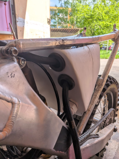
1779187306109.png

The threads are crossing over now I guess, but I just want the #1 bike up and running because the weather is amazing right now and I can't ride.

I've bought _another_ assymetrical subframe, but the only one i was able to find was cracked. I plan to take it to a friend with a TIG and patch it up. I'm still not sure what to do with all those parts and what will go where, but I've discovered that the seat that came with #2 is actually for the new subframe, which together with the fact that the EM200 controller won't fit in my box is making me lean into making a simple carrier plate for the 2nd frame and working on fairings then. We'll see about that in the #2 thread later though.

So, what else is new? I've been trying out harness.design and love it so far:
1779187534732.png

It allowed me to finally make sense of all the wiring, document it all properly and plan the changes i wanted to make. The biggest annoyance currently is the unfortunate situation with the 72V line going all the way to the handlebar switch. I need to make this be a foolproof thing, but unfortunately i'm still missing the Deutsch connectors i need for the 12V distribution box that might also handle that specific thing. Having it all in software allows me to plan out the connections much more easily though.

Similarly, I want to get rid of that cheap plastic switch i had for S/R/mode, but the buttons i've ordered still will take a while, so i'm inclined to keep the current broken one for now and only tackle the stuff necessary to get the bike moving again.

After some consideration, I decided to not use the cable throttle again. I just wouldn't feel safe knowing it can fall out at any time, the new cable i put on is already bent and damaged, and it just doesn't seem worth it to try to remedy all those problems just for the cable feel and variable cams. I'll be putting the surron throttle on and already ordered another one for the #2.

I've also made a snap decision and bought a DKD display. My own display will take a while to get ready and this is a known working solution, so might as well. For whatever reason when used in CAN mode it needs BMS data on CAN to show the battery status as well, which would be great (and a great idea to add for the battery in #2) but since my current battery doesn't expose that, I think I'll keep it in LIN for now. Still not decided what parts will go where - ideally I'd sell the first battery instead of the 2nd one, as I see the first one as a design dead end, similarly with the subframe. Selling it means i can move on to the new subframe and fairings for a battery that actually doesn't protrude past the gas tank. The DKD display might then also go for the sale bike as it looks trick and is simple enough to show the basics.

P.S. One more interesting thing; I don't have a photo, but I machined a set of 10mm spacers that will go between the controller terminals and the battery cables. This is a very critical connection, but what this will allow me to do is to angle the thick battery cables arbitrarily; with the semi-recessed terminals, it's impossible to get the cable to go from the wrong side of the controller, as the large connector plate would then rest on the separator plastic, fuse or another terminal; see image for reference:

1779190936112.png

Raising them will allow me to have much better flow of cabling, hopefully without compromising the contact resistance. I've made them from aluminium which should have decent electrical properties, and over just 10mm it shouldn't really be a problem, i hope. I will of course need longer bolts as well. The phase wires are less of a problem in this regard because they're much more widely spaced, the cables are much thinner (ironically, since they actually carry more current - i really oversized the battery connections on this bike, didn't I?) and the connector eyelets are smaller.
 
Last edited:
Continuing directly where I left off, the plate risers were a really good idea, but the cabling is still messy in that box... It is nicely covered and protected and most importantly the controller doesn't flop around anymore on landings, but I think my idea for only central carrier plate and side fairings will end up much nicer in the end.

The most important thing is that the bike is finally back on wheels:

1779697031403.png

I removed all of the switchgear for now and only left the on/off button. Super clean experience, though I miss the reverse button already. Those will come back soon, as I already have a couple different switch options bought to replace the fragile plastic one, but for now the focus will be on getting the bike #2 rolling as well.
 
It's been a month, so just a small update on bike #1 - running well, box holding up great, i like the clean-no-button look but miss my reverse, so I'll need to get the accesories back on it. Something is still knocking around, i think it's the charging fuse enclosure, as the controller is now rigidly mounted; that will be fixed with the new distributor box once i get around to it.

Surprisingly, with the handlebar back in OEM location I don't mind the ergonomics at all. The front end is working well and I have no problems with the suspension. It's working so well, in fact, that when my friends on Surrons jump from the small roots and logs, this bike stays planted because the suspension just soaks up everything.

Ironically, this means I could go much faster, but with no sport mode i keep running out of steam. The medium term plan is to get 520 chain and 14-52 gearing (would also help with chain height). The short term plan might be going to 16-60 until the current chain lasts. The long-term plan, of course, is a 96+V battery.

I've also noticed that the price of those frames has been dropping steadily. I bougth the 2nd one for 3300PLN; and now it's trivial to find a complete CRF frame for 2500, while cheaper 125cc yamahas go for sub-2000 figures. Great time for building, so I really want to get #2 running now.

Oh, and I'd forget! Remember how I had to grind the battery enclosure to make it fit the frame? At that point I was angry and impatient, so did it with an angle grinder a bit overzealously. In one point, i pretty much removed all reinforcement, leaving just thin resin on a corner...

1782295735180.png

I can't really blame anything but myself on this. Thankfully, with polyester, this should be a relatively simple fix/patch.
 
Last edited:
Was supposed to work on the battery, but went back home late and decided to rest by restoring my reverse instead:

1782382419225.png

This is the new style of button I'm trying out. They come on Aliexpress in multiple variants, but most notably, some are made in plastic and some (like the one in the pic) in aluminium. The cable routing inside of the switch enclosure isn't great and especially with a replaced, thicker cable, prone to shorting/bending during mounting (especially because the buttons used aren't really meant for direct cable soldering...). I eventually got it to work reliably, though; i might end up replacing the buttons and resoldering everything, but for now I wanted to try the form factor. At least when it's fully assembled, it all stays in place reasonably well and doesn't stick out nearly as much as the old plastic switch did.

On that note, since I don't have a sliding bar for 3-mode switch anymore, i reprogrammed the controller to use a simple toggle between modes (on the back button). Honestly the only reason for me keeping this on is for allowing beginners to get on the bike with a bit more safety. I've changed the main modes to also draw 200A from the battery, so on my "walk" - L - mode, it can really scare you with the initial pull (and a small wheelie) but will cut the power right after at about 10km/h. It's pretty perfect for learning the actual throttle response without the risk of looping the bike out, frankly.

The downside, of course, is that i have no idea to know which gear the bike is in now. It's not much of a problem, as it defaults to H on reset, and the S-mode button is a physical latch, so visible at a glance. I'd still love to go back to my display project for a nice overview at some point.

Wiring wise, I reused the harness from the previous switch; it used very thick 7x18AWG cabling which is really an overkill. Not just because of the thickness, but because those switches actually share a ground in the Votol controller, so it could just as well be connected with 4x cable and a single 4-pin plug. It would require rewiring everything on the controller side, though (I have 2pin, 2pin and 3pin there right now, swapped to Sumimoto connectors), so i decided to keep it as is and only redo everything once I'm 100% certain what layout/cabling I will want (or maybe for the next bike).
 
While I'm waiting for pricing for the battery insides for CRF #2, I've decided to finally push with some upgrades, as we're increasingly riding in the night time to escape from the heat:

1782910494340.png

This is a KTM-style lamp, which means it relies on two poles in the fender to slide into. Of course my fender didn't have them, but I 3d-scanned it and made a simple bracket that bolts underneath the fender, then printed with just PLA. Fits very well, might reprint it in ASA later, but for now the priority would be to get the 12V system going to actually use this lamp, because it's only mounted for now, with no power routed :)
 
Tiny update - lamp mount held up fine through the weekend. Still haven't wired it up as I'm working on the power distribution box. I've realized having some switch there would be a good idea to prevent the DCDC from discharging the battery, but any switch there would also necessarily work on the 72V line, which ideally means some sort of precharge. I've managed to avoid it all this time by relaying on bms precharge but since i don't have an easy way to quickly cut the battery off at bms level (other from the app) it's just not going to be convenient.

My current mitigation/short-term plan is to use a pull key with an antispark XT90 connector. It wouldn't route all the power, just the charging port and the 12V system through a common 30A fuse. It's a bit crude but should be reasonably effective, as long as I can expose it where it's easy to disconnect but won't cause issues during riding.

I also figured that fitting 3 12V fuses in my small box might be a bit of a challenge. All existing small fuse boxes are still too big and bulky and rely on connectors. My current plan is to buy a bunch of inmolded fuse holders, and add slots in the 3d-printed enclosure to trap them with a simple push - maybe a bit of hot glue to help stay in place. That way i get two nice wire ends i can directly route to my 12V connectors and bars. Considering my power wires are going to be 18AWG, i think having a 5A fuse on each of those is a good idea in addition to the main 30A fuse for the entire box.

Just a reminder, the box is supposed to:

* Take 72V input straight from the battery/controller terminals
* Fuse 30A
* Go to charging port (currently largest charger is 15A but i might up this later)
* Second branch: go to 12V DCDC through XT90 pull key
* 12V splits in 3 and powers
* * headlight (35W)
* * USB socket (with fast charging - up to 50W - isn't it ironic how powerful phone chargers are these days)
* * My custom display (and I'll put a 12-to-5 dcdc in there)

So the 12V lines will likely get 5A, 5A and 1A fuses.
 
Back
Top