2WD (dual motor, two wheel drive) Trike build.

That is a very cool build, llile! I does seem a bit high C/G though. Do you have plans to narrow it and tilt? I used to be able to ride on two wheels of the three and not fall over (too often), but that was a long time ago in a Galaxy far, far away.
otherdoc
 
Looking good llile. I've always wanted to see someone test a dual front hub tadpole.

But just in case, for plan B you could always reverse it (delta style) and test a reverse steering delta. It should be virtually impossible to tip while under power. :D

Edit: In fact, I don't think it would be easy to tip any rear steering trike, delta or tadpole, while under power or just coasting.
 
llile said:
Well, 50 years later, I am that guy.
You, too? :lol: :oops: I've stopped actually looking for bikes the last year or so, though I still take any that are offered, rare as that is, because my presently-completely-disorganized parts-bikes pile is almost half of my back room. :shock: (not including the two motorcycles, which take up another 1/8 of it). (I had mroe stuff until the city decided I shouldn't, and had to clean it all up with a still-broken (fractured) ankle--most of it was moved inside, but some of it I couldnt' find room for).

Probably need to start throwing out old wheels, I really am getting too many of those around. But you never know - IT MIGHT COME IN HANDY SOME DAY!
I can never bring myself to do that, becuse everytime I start to, I discover another use for some part of the wheel.

Axles and nuts and washers make good bolts to hold stuff together, or spacers for things, etc.

Always needing more bearings to replace worn ones or ones I dropped and can't find again.

Hubs can often be adapted to other purposes, like jackshafts, or even spindles for steering linkages.

Rims...depending ont eh type could even be used as parts of a frame (decorative, at the least), when cut in pieces as needed. Could even make stout fenders out of them if you can bend them the other way round. :) Steel ones can be welded together in various ways to make barriers or decorations, etc. Stack a bunch the same size and tack weld them into a cylinder to use for storing stuff in.

Also, remember that if you get "desparate" for the right lenght spoke, you can do what Karma did, and cut the elbow/flange end off, insert the spoke thru the hub flange, bend around and twist (like barb-wire fencing) around the straight lenght of spoke. install the threaded end into the nipple/rim just like normal, and lace up your wheel. Has worked for him for qutie a while, IIRC.
 
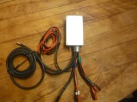
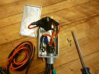
Here is an important junction box I've just completed.

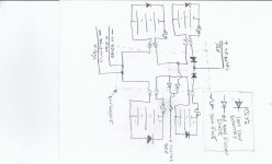
It takes four batteries, placing them two in series, then two sets in parallel, to get 72V out of four 36V 15 AH PINGs. Wiring diagram and pics attached.

Why go to such trouble? I have two e-bikes, and the batteries must be standardized between them. One of them uses a 36V battery, so the rest of the stable also must use that bettery. PING doesn't make a 72V battery, the highest they go is 60V, and I was set on 72.

There is a 36V tap in the middle, created with two diodes, for lighting and accessories. I could not find a reasonable DC-DC converter that would allow 72V (up to 100V!) input, but did find a 12V DC-DC converter and a small LED driver that will make good lights. I may also put a 12V plug on board, dunno yet.

The heavy current diodes are 100A 100V Schottky's, and the lightign diodes are 6A silicon diodes, 400V. I need to add a fuse int he lighting line somewhere, maybe at the DC-DC converter.

All this electrical complexity makes this job a lot more fun for a sparkie type like me.


P1050551.resized.JPG


j-box wiring diagram.resized.jpg


P1050552.resized.JPG
 
It is a pretty complicated rat's nest of wires, so to test it, after I had sealed it up, I clipped some 9V batteries onto the Andersons with alligator clips, and tested various voltages in other spots. This is better than testing with full 36V batteries, and finding out there is a cat-whisker short between two terminals. KaPOW!


This battery stack should be good for 2160 watthours, or more than 50 miles range if this bike is as efficient as I hope it to be.
 
Bench test!

Video here: http://youtu.be/YzAbgMM3JB0

Tandem motor wiring is complete!

Plenty of issues left to solve:

One wheel is out of balance as you can see in the video
Cycle Analyst isn't calibrated - I have no idea if it was really going 50MPH
human-powered drive train isn't complete
gear shifters aren't installed
Seat needs a lot of work
Fairing mounts aren't done
Cycle Analyst "dashboard" mounting bar isn't installed
Needs mirrors and lights.
 
As one can see in this post, I am having some battery/motor problems. It may be, unless I can find an elegant way to dial down the amps, that I don't have a big enough battery pack. Unfortunately a bigger battery is also more expensive, and I'm trying to economize right now. Creative solutions are needed.

Otherwise, mechanically the bike is in pretty good shape right now. Quite nearly complete. Photos coming.
 
The only semi-elegant (if even that) way I know of (short of programming the controller) to dial down the amps significantly without causing cutout of the controller/motor at high loads is to modify the controller(s) shunt(s).

--Easy way is to desolder or cut one shunt entirely, if there are multiple shunts, to reduce the current by a proportional amount (25% if there are four, 33% if there are three, etc).

--Alternately, filing off some shunt material or nicking/crimping a shunt with cutters or a file or something can be used to slightly (or greatly) increase that shunt's resistance. But this is more time-consuming to do, by trial and error.

If the controller is programmable it can be done more precisely without physical modification.


If the CA has the option for current limiting, then depending on version it should be able to simply throttle back as current nears the limit, so it doesn't simply shut off throttle once the limit is reached.
 
llile said:
Bench test!

Video here: http://youtu.be/YzAbgMM3JB0

Tandem motor wiring is complete!

Plenty of issues left to solve:

One wheel is out of balance as you can see in the video
Cycle Analyst isn't calibrated - I have no idea if it was really going 50MPH
human-powered drive train isn't complete
gear shifters aren't installed
Seat needs a lot of work
Fairing mounts aren't done
Cycle Analyst "dashboard" mounting bar isn't installed
Needs mirrors and lights.
Cat needs fixing too :mrgreen:
 
A separate thread details the sad tale of woe and intrigue wherupon I ended up changing the current limit in my controllers via a shunt vasectomy. I now am running two 20A controllers (originally 40 amp) and one 72V 15AH battery stack (2-36V batteries)

Bike has ridden under power up an down the 800 foot driveway. A little squirrelly, got some wheel balance problems in the right wheel, one of the brake rotors is warped, making a rub, and the motors are a little touchy on the throttle sometimes, but the bike runs. Hooray!

LEft to do:
true and balance all wheels
deal with shifter cables
change handlebar angle to match my wrist angle - it isn't right
Make a real seat instead of a chunk of foam ziptied onto a tube
Cycle Analyst quits reading speed at 30 mph - dont' understand this yet
Buy some good tires instead of the junkers on there now
Buy a second battery
Take it all apart and paint it.


Long term:
I will probably have to lower the center of gravity as one fellow suggested, doesn't feel right. This is not that hard, as the major component that would have to change is removeable from teh rest of the bike.
 
Been out for some 1-2 mile spins. Bad problem with shimmy, traced to a slight tolerance in the front head tube bearings. (Like a 2 wheel bike, I used head-tube-sized assemblies to hold the front wheels. although the tubing is exactly the same size as a mt bike head tube, there is a little play in the bearings). One of the front wheels can play just a few thousands either way in the bearing. Amplified by leverage, this translates to maybe 1/2" play at the wheel contact patch. Play results in a tendency to rattle back and forth and oscillate when going at sustained speed.

THis isn't happening on both fronts, only one, and since the bearings were cabbaged from several bikes, there is a mismatch. The one that works best has sealed bearings, one piece, the other one has old-school bearings and races.

Tried removing the springs that comprise the front suspension, this helped, but it isn't a solution, just a test. This does improve the center of gravity by 4" lower, so that is a plus. There is a little imbalance in the tire (haven't bought my good Schwalbe Marathon Pluses yet, jsut an old scrap tire) but once the tire is removed, no wobble in the motor and wheel. Tire imbalance translates to wobble unaccaptable over 20 MPH. Tried tightening everything down, preloading the bearings, so far not much luck. Also ended up causing a flat when I put the tire and tube on last time. Hate it when tires are so damn tight you can't put them on without excessive force on the spoons, inevitably pinching the tube. Been changing bike tires for 50 years and still can't do it every time.

I wonder how to control the play and shimmey?
 
Used a strobe light (did I say I have a whole lab fulla equipment to use here?) to calibrate the Cycle Analyst. I believe the readings I see on the screen now, not that I didn't before but I am suspiciopus like that.

Wierd problem with CA. If the tire speed is over 39MPH, the Cycle Analyst begins to register zero speed. The CA is using feedback from the motor windings to measure speed, no discreet speed sensor. MPH limit is set high, doesn't make any difference.

What could cause the CA to quit at 40 MPH?
 
SHameless Plug warning:


I buy chrome moly tubing from these guys:

http://www.airpartsinc.com

Air Parts in Kansas City (not to be confused with the other Air Parts company)

Catering mostly to the experimental aircraft crowd, they sell a lot of cromo tubing to motorcycle, bike, and other frame builders. They are used to custom orders, can answer a lot of questions, and are used to strange and interesting projects. Log on to the website if you need tubing! I've bought tubing from then for 20 years, always satisfied!
 
llile said:
Been out for some 1-2 mile spins. Bad problem with shimmy, traced to a slight tolerance in the front head tube bearings. (Like a 2 wheel bike, I used head-tube-sized assemblies to hold the front wheels. although the tubing is exactly the same size as a mt bike head tube, there is a little play in the bearings). One of the front wheels can play just a few thousands either way in the bearing. Amplified by leverage, this translates to maybe 1/2" play at the wheel contact patch. Play results in a tendency to rattle back and forth and oscillate when going at sustained speed.

I wonder how to control the play and shimmey?

More work on the front end has revealed a critical weakness in the frame. Although it is plenty strong in one direction, it is weak in torison. As the wheels roll along under motor power, the frame torques in one direction, then relaxes back, causing the shimmey. Shimmey dissappears when I back off the throttle, or when I pour on the electrons. Exacerbated by some mechanical slop in the bearings, this is a show-stopper. Mechanical slop is fixed, but the shimmey is still unacceptable. I could weld on a bunch more struts, but it is a frankenstein as it is already. I'm scrapping the front end and rebuilding it, also lowering the center of gravity. Making the whole front end much simpler and probably lighter, out of bigger tubing to handle the torque. Just ordered the steel. This is a major setback, but hey - if you don't make any mistakes you aren't learning anything.

I'm going to try out the leaning geometry for a spin before I make a decision, but I am thinking the leaning frame is also gonna have to go. I have seen motorcycles built this way, however this may be too much going on. Heavy batteries make it flop over and hard to right again. Lower center of gravity will be mandatory if I can't lean the bike. Once again, I am doing this to try and push the envelope, trying some crazy ideas to see if I can make them work. If some of them are unworkable, that's expected!
 
Welcome to the trike club again, llile! That is the dilemma. Check out the new Tripendo to see how they tilt a trike. If you don't tilt it has gotta be low to keep the C/G low or stick heavy stuff low like batteries and the motor. Higher is better to be able to see and be seen in traffic, but then..........you can tip over on a non tilter. Also the Canadian firm makes a Varns trike that tilts, but it is a delta.
otherDoc
 
Here is a video of the Tripendo leaning trike:

http://www.youtube.com/watch?feature=player_embedded&v=BZ9dND_ArVg


"
Code:
 Steering

    The steering trapeze under the frame of the vehicle safeguards exact and more pronounced turning of the inner wheel when changing directions.

    Turning cycle: 5 m / 16 feet
    	
     	 	 
    	Operation

        Right lever: Adjustment of inclination.
        Left lever: Adjustment of the degree of turning of the wheels.
        Example left turn: Pull left steering lever backwards, push the right inclination lever forward.

    The vehicle is, however, only steered and inclined via the turning lever (left lever). The right lever merely serves the easy correction of the inclination and keeps the vehicle vertical at very low speeds. This steering principle is easily mastered after a short introductory period and is decisive for the unique fun riding a Tripendo offers.


http://www.tripendo.com/EDEFAULT.htm
 
Well played, Tripendo. The rather complex mechanism to lean all wheels, with a shock absorber, is a nice solution, but beyond what I want to tackle right now. Just leaning the back wheel, with me and the batteries, should make the bike a lot more stable.

Now here is my question: on a leaning vehicle, (3 wheel motorcycle, tripendo, what have you) is the ability to lean unrestrained within the limit stops, or is it mitigated by some kind of damper/spring/etc?

And then the other question: How far to lean? I have tried to estimate how far I am leaning on a tight corner on a two wheel bike. I have yet to find a corner that feels "tight" that I feel OK about navagating at faster than 25 MPH. Several tests of this showed that real road radii are quite large, and a road that is built for 45 or 55 MPH has radii much greater than this. Once years ago I raced a bike down Trail Ridge Road, from 11,000 feet to 5,000 feet, in Colorado, pacing every car easily. I found the bike could handle corners much better than the cars, who pulled away on the straights but chickened out on the corners. For a bike, these were all very generous curves, and I could navigate them without much trouble at all.

In experiments closer to home, I found a sharp right hand turn lane at a stoplight. On this particular corner I was able to go back and pace off that I had executed a 150 foot radius at 25 MPH on a two-wheel bike, and it was a real white-knuckler. Didn't really want to be going any faster. How far was I leaning? Drat, 25 years ago the physics to do this problem was still in my brain. I have a mind like a steel sieve. It feels like quite a steep angle, but I can't measure it while riding. Best I could do is get someone to snap a picture when I am going around a corner.

Currently, I have adjustable stops on the leaning mechanism, and have them clamped all the way down, eliminating all leaning. It is annoying to have the bike flop over when I am working on it. If I keep the mechanism when I rebuild the bike, should it have any spring or damper, or just be free to move? And how much of an angle should it allow? Hmmm...
 
We have a gigantic database showing how far motorcycles lean - Youtube! Every knucklehead with a bike and a cam wants to take a video of it. Here is a shot of a guy on a Honda gold Wing (a rather safe and sane sort of motorcycle) on a curvy mountain road, at around 65MPH. He is leaning about 14 degrees from vertical.

Obviously this is one datapooint, but it starts to give me the idea that we aren't leaning 45 degrees (that is what it FEELS like!) when we are tearing around curve. Now to hunt up some more motorcycle videos, that aren't so safe and sane.


Given that my friend who has ridden a pedal powered trike for some years, has some concern about corners, has had it up on two wheels before, but not flipped it, and given that a person will naturally lean the body around a curve regardless of the bike, I am "leaning" toward restricting the lean to a rather small angle. Less than 45 degrees, surely. Maybe less than 30 degrees. It becomes very impractical if the bike can flop all over the place when parked.
 
OK, I found a real knucklehead. This guy is riding a crotch rocket, slolomming in and out of heavy traffic in a big city. In this screenshot he is going maybe 40 MPH? Speedo is hard to read. I'm estimating he's leaning at 42 degrees, and this is about as hard a turn as he can make at such a speed, since he is showing off for the camera.

So, is 45 degrees too much? I am certainly not going to be slollomming in heavy traffic like this nut, maybe that is too far. I am confident that I will keep the bike to a reasonable speed on turns, use my own not-inconsiderable weight to lean in the seat, so maybe I don't need such an extreme range. Such a range of lean angle is very inconvenient all the rest of the time.

I can't imagine that a bike wheel would even stay in contact with the ground at greater than a 45 degree angle, it seems like it would stop gripping and just slide, causing a wreck.

 
This guy limits his trike to 27 degrees: "The geometry has a natural limit that causes the tilt to lock at about 27°."
http://www.jetrike.com/geometry.html

He also has some nice charts showing the relationship between banking angle, corner radius, and speed:
http://www.jetrike.com/why-does-tilting-matter.html
 
lclarkberg said:
This guy limits his trike to 27 degrees: "The geometry has a natural limit that causes the tilt to lock at about 27°."
http://www.jetrike.com/geometry.html

He also has some nice charts showing the relationship between banking angle, corner radius, and speed:
http://www.jetrike.com/why-does-tilting-matter.html

Oh man that is just the analysis I was looking for! His charts show why the 27 degree tilt angle is used - a typical road has a gigantic turning radius, his charts go up to 20 meters, which would be rather low in fact for a road that is built for any speed. At those kinds of raddii and larger, 27 degrees is all you need. The Knucklehead int he bike video was making much tighter turns at much higher speeds than you'll likely find when driving safe and sane.

Although most roads are banked, the problem comes at a situation like this: You approach a left turn on a green light at the speed limit, at the end of a good hill maybe. You are going to negotiate a non-banked, rather tight corner. This may in fact be one of the worst cases for cornering. Hope you have good brakes! A right turn would have been sharper, but you'd come to a near stop to negotiate it first.

The geometry calculations showing ideal Center of Gravity for a trike are very valuable. I didn't have this information when constructing Version 1 of the frame, and so just took a wild guess. I might be able to use a tighter front wheel width, if I have the COG dialed in with version 2. Will have to CAD up some sketches to check on all these dimensions.

Thanks!
 
http://www.jetrike.com/why-does-tilting-matter.html

So, applying the principles here, I made a few calcs for my bike:

Curb Weight, no batteries: 122 LBS/ 55.45 kg. I know, it is a tank. That's OK. It has a lot of motor. It isn't a cattrike.

Front trike wheel width: 43 in
Wheelbase; 65 in

I estimated COG using some spreadsheet calcs, weight specs for battery, me and the bike, and rough measurements of relative positions.

Rough esitmate of Center of mass, including me, batteries, and bike, approximately 33 inches above road surface and 46.88 inches in front of the rear wheel. Vehicle is kind of loaded to the front, but a load of groceries would shift it rearward somewhat. Once again proving it isn't a cattrike.

Now, the angle between the COG and the outside contact patch determines how fast the bike can take a particular corner. But since it is a triangle, the "outside contact patch" is effectively moved inward, as the triangle footprint of the bike diminishes from front to rear. If the bike tipped, it does not tip on the front wheel, but on the line between the front and rear wheels, so this projected wheel width effectively reduces the width of my bike. I'll call this a "projected" contact patch just to have a name for it.

Using some string, tape measures, protractors, levels, a handy straightedge, I measured versus angles of tilt for the frame, and translated them into angles from COG to projected Contact Patch,and thus into maximum cornering speeds on his charts.

Here are some results:

No leaning frame, current front end geometry and high COG: Angle COG to Contact Patch (projected) 26 degrees Max cornering speed 15 mph on a 25 ft radius.
5 degree lean in trike frame - Angle COG to Contact Patch (projected) 30 degrees 16.8 mph or a 12.5% increase in cornering speed over fixed frame
10 degree lean Angle COG to Contact Patch (projected) 35 degrees 18.75 mph or a 25% increase in cornering speed.
15 degree lean, because of the geometry of the bike, did not materially increase this angle, so that may be the limit of practical frame leaning. Leaning more than that feels really awkward, flops around.

The racers in the link above are leaing more than this, however I am not a racer, I am a commuter and grocery hauler. Leaning the bike more than 5 or 10 degrees makes a floppy, awkward ride, complicates steering geometry, and isn't for me. Bt a 5 degree lean would make a material improvement.

Redoing this calc, assuming I lower the center of gravity by 8" after major abdominal surgery on the frame I would be able to take the same corner at 18.75 mph, having a 35 degree angle COG to Contact Patch (projected), or already 25% better than the current bike with no complicated leaning geometry.

If I could tilt the rebuilt frame at 7 degrees, according to the crude measurements in the garage, I'd have a 40 degree angle, and could take the same corner at 20.6 mph for a 37.5% increase over the current bike but only 10% better than a fixed and lowered frame.


So I can conclude that lowering the CG 8" does as much good as any tilting I care to do with my frame now, but lowering it and tilting just a little might improve cornering by half again.

Or I could argue the other way and say that after lowering the CG, leaning only gains 10% more than a fixed and lowered frame. So If I argue this side, should quit fooling around with leaning and just weld the damn thing up. Once the frame is lowered, the extra gain by leaning is diminishing returns. i would likely regret that last sentence halfway through a flip on a mountain road someday.

Hmm. I am going out to take a ride with the current leaning geometry enabled to about 7 degrees before I decide whether to abandon the leaning experiment altogether in favor of just lowering it and no tilting.
 
Back
Top