400W for 12mph: Why is my bike so inefficient?

cwah said:
How do I know the Rshunt value of my controller? And how do I change that?
The RShunt value is usually on a printed sticker on the back of the controller. If it's not there, ask the guy who sold it to you. You DON'T change the controller's RShunt value, you change the value in your CA to match.
 
As is often the case, reading the manual for the CA (or in this case the FAQ on the ebikes.ca web site) sheds light on the problem:

I just got a Direct Plug-in Cycle Analyst, but how do I know the RShunt value of my controller?

Ideally, you will have some other current reference and then you can compare the readings on the CA with the known readings of another amp or amp-hour meter. So if the Cycle Analyst says 27 amps while a reference shows 19 amps, then the CA's RShunt value needs to be increased by 27/19 = 42% higher. By default it is set to 1.000 mOhm, in which case the correct value for RShunt would be 1.42 mOhm. If you don't have another current reference, then you can get a decent calibration value based on the current limit of the controller. Look at your continuous amperage draw (second screen) while riding low speeds at full throttle. If the CA says 53 amps while your motor controller is limitted to 20 amps, then your best guess for RShunt is 53/20 = 2.65 mOhm.

The exact value of RShunt can vary quite a bit from controller to controller even from the same manufacturer and batch. The 6 mosfet Infineon controllers are typically between 5-6 mOhm, the 12 mosfet controllers are more often between 2.5-3.5 mOhm. Crystalyte controllers can range from 1.1 mOhm to about 2.6 mOhm. The eZee controllers are usually between 1.3 - 1.6 mOhm.
 
Thanks guys. I just sent a mail to Lyen.

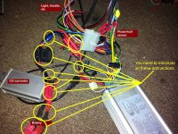
Here is my wiring set up (for now):
controller_wiring.jpg


Is it all right? The ATX connector is the only one that is cheap with 24 pin able to handle higher amps.
 
cwah said:
Damn, I forgot. The turningy is limited to 60V. It doesn't work with my system :(

You can try measuring amps (no-load) with a multimeter if you have one. Normally even cheap ones can measure up to 10A DC.

Hope this helps.
 
cwah said:
Is there a simple way to measure the electrical loss? Can I do that with a voltmeter?
Probably not with what you have got, depends on how good and accurate meter you have. Unless you have a many hundreds of £, the accuracy and resolution of the resistance scale of a cheap DVM probably will not be enough. My idea of resistive losses, is only a shot in the dark really, just based on what I can see of the wiring.

The ATX connector is not going to be an issue with regard to the power losses, it is only the main thick power and phase leads that are going to be causing an issue with regard to losses in power from battery, via controller to motor.
Any connection or splice has resistance, any lengthy of wire has resistance, thicker wire has less resistance. Any resistance, when a current passes through it will have a small voltage drop across it and therefore a loss of some power

How many junctions do you have between battery and controller? Including soldered splices that are not connectors?
Just looking at your picture I can count at least 8 on the battery to controller wiring. What a hash up of wire. Do not want to sound rude but that really needs sorting.
Even those fuse holders are not brilliant. At higher amps, I have melted three of them. You need to clean up the grey corrosion on the legs of the fuse before you insert the fuse, that helps but is still extra resistance
I have one single connection between battery and controller now, with no extra lengths of wire between. I ( stupidly possibly) even stopped using a fuse, as I can't find a holder good that won't melt at 80 amps


Think, even a soldered splice is effectively two junctions to the electric flow; end of one bit of wire to solder, solder to next bit of wire. Virtually zero resistance admittedly, but it all adds up, and the more you have, the more chance of a bad connection somewhere


On another track, how easily is the wheel spinning? What are the wheel bearings like? Drag from brakes etc?
 
controller_wiring.jpg

Coming from the controller, a spliced connection to a used bullet connector, then to that horrid blue Lucas style crimp connector to the fuse. Should at least have just one connector between fuse and controller, with no splice.

Just think ..one pair of connectors, the amount of junctions you have....Wire to connector. connector to connector, connector to wire. Three interfaces on just one connection. Multiplied by the number of connections...then going back again as the power returns to the battery.
That is before we even look at the phase wire connections.

Lyen uses big spade connectors which he will sell you. See them in this next picture.

Get him to send you a bag of 20 or so of each

file.php


Where you need to tap in to a wire to connect stuff like the 12v convertor, strip back the wiring insulation and tap in, solder, and heat shrink. Do not cut it to fit an extra connector.
 
Ok, just strip out the sillicone of the wire in order to add the 12V adaptor.

I know I have a lot of connectors lol, but it's still a "work in progress" set up, I'm planning to remove a lot of them once I'm happy with the set up. For now it's still a lot of trial.

Why do you recommend spade connectors? The bullet connectors in red are supposed to be good? I think the blue one is the worst and I'll remove them as soon as I'm sure about my set up.

I have quite a lot of work to do to clean everything :lol:
 
Those spades that Lyen sells have an extra tab inside to make a full area contact surface.They are much higher current rating than the bullets and also they can be crimped .

Those spade terminals are different to any I have seen for sale in the UK.If you can source soem the same then let me know

Crimps are better than soldering, for lower resistance.

As I said before, this may not be the issue,,,but it is going to cause a voltage drop and losses wether this is the main problem or not.

If this wiring is just temporary, then try this. Connect the battery direct to the controller..No fuse, no 12v convertor, just battery to controller, leave the small red 'power on' wire disconnected and connect that to power via a switch. When you connect battery to controller, male sure power wire is off. If you can first connect the two power wires via a pre charge resistor, then quickly, within seconds, take out resistor and connect red to red.

Do you still get the high current drain with no load with a direct connection?

if you still get the high current under no load...then I have just wasted both your and my time, :wink: but at least something else ruled out
 
True about the connectors, but if they were where all the watts were going, you'd see the melted ones.

I'd do a soild connetion to the fuse ( mabye better one) right on the battery, then one set of good RC 4 or 5 mm bullets to connect to the controller.

Charging with an RC charger? That will tell you how many milliamphours the charger used to recharge, and an accurate distance on that ride + math even I can do will give you a wh/km number you can compare with your CA. If they are way different, your CA is whacky.
 
dogman said:
True about the connectors, but if they were where all the watts were going, you'd see the melted ones.

.

Not necessarilly, there are a lot of connectors there, they all only need to be dropping a bit to make a difference
 
Well, when I've dropped enough into some connections it was obvious. It could well be that he's seeing 50w gone into warming connections. I think 100w would make em noticeably warm if he rides more than 2 miles. Does he ride more than 2 miles?

In two miles, you'd not see your motor getting all hot yet.

What I haven't seen yet, is any reason to think his CA is accurate.
 
50 W is about the same as a lot of soldering irons, so if that much power was being lost in the connectors they would indeed get pretty damned hot. Even a watt lost in a connector makes it feel warm to the touch.

I think we can now be pretty sure that the CA was way out in terms of power and current readings, because it was still left at the default R shunt setting. Once that's set correctly for the controller shunt value I suspect we'll see the true power that the bike is using, which will probably be a lot less than 400 W for 12 mph.

The good news is that if this turns out to be the case then the size of battery pack needed to do the needed range and the desired speed will be a lot smaller and lighter.
 
Yes, you are both correct, when you start putting figures to it, any losses in all those connectors are probably irrelevant..sorry for wasting your time cwah.
Maybe I have been worrying too much about getting short cable runs and reduced number of connectors on my bike. Never actually worked it out or put figures to it, just thought losses would have been more, maybe I have been worrying too much about short thick cables and few bigger connectors on my bike. :(
 
NeilP said:
..., maybe I have been worrying too much about short thick cables and few bigger connectors on my bike.
Definitely a worthy cause for performance reason especially for wires that carry high current. Minimizing the voltage drop can never be a bad thing.
 
I seem to remember Ed Lyen telling me he uses the same value shunts all the time. I have an e-mail at home with this figure.
He does not do an exact measurement, he uses the manufacturers shunt value then factors them depending how many are fitted.
If we get a picture or indication from the OP how many shunts there are, and I post back when I get home, with the figure of the individual shunt value Lyen uses ( It is in one of hi smails to me), we can work out the exact shunt value required. OK, so it won't be a 'calibrated figure' but it will be within reason good enough
 
OK, well the shunt value on my 18 FET controller is 1mΩ, according to Ed Lyen.
There are 4 individual shunts
therefore each one is 4 milliOhm or 0.004 Ω

As soon as we know how many shunt wires he has we can work the actual figure out
 
Guys, Lyen told me to that the controller has 2 mOhm value. So I'm going to change the one from the CA and see if I still have high value.

I'm going now to desolder the 12R resistor then I'll tell you the result if the controller still work. :)

Thanks for all this warm help
 
cwah said:
Guys, Lyen told me to that the controller has 2 mOhm value. So I'm going to change the one from the CA and see if I still have high value.
You won't. What ever you saw before will be cut in half now. That's a lot closer to reality but still too high. At WORST it should take no more than 150W for you to cruise at 12mph on flat terrain. So you may have to determine the actual controller RShunt value using the reference method mentioned by Jeremy earlier in this thread.
 
Removing the rear one will only affect the voltage settings of LVC and HVC.

Do not remove the small surface one on the front though.


If Lyen told you 2mOhm, then I guess that will be close enough.. out of interest, tell us how many shunt wires you have..i am guessing it will be two.

I had an external shunt CA, that e-bikes.ca calibrate accurately before selling. I used that to exactly calibrate my lyen controller shunt. I think I ended up with a value slightly less than 1 mOhm, 0.950 or thereabouts.

i tried riding at 12mph today, and ended up with a constant reading of about 120W on my bike, and that is with 26 inch wheels at about 35psi, smooth road tyres
 
NeilP said:
i tried riding at 12mph today, and ended up with a constant reading of about 120W on my bike, and that is with 26 inch wheels at about 35psi, smooth road tyres

Pretty much exactly the figure I predicted when this first came up! Nice to know that theory can match reality now and again.....
 
Jeremy Harris said:
Nice to know that theory can match reality now and again.....
Surprised, surprised!

cwah: You'd have to open up the controller. If I were you, I would not do it. I would take it slow and get only one thing done at a time and done well.
 
Back
Top