40T, neodymium magnets, plasti dip cycle test

Dak77 said:
Since you're into the more obscure cell testing, another future consideration , maybe a Queen Battery qb26800 . If that thing has even decent cycle life , it would be very interesting.
I saw that battery here, Thunderheart did it but something turned me off of it? probably because they wouldn't sell me 1 battery for testing and I asked for a quote on 400 cells of the 26800 and they wouldn't give me a quote

I bought a MNKE 26650 5000mah from 18650 Canada for testing but I hadn't realised I bought into a pre-order, that was 2/3/4??? months ago, its been awhile and its still pre order. Queen Battery has them too but they don't want to sell me anything
 
goatman said:
Dak77 said:
Since you're into the more obscure cell testing, another future consideration , maybe a Queen Battery qb26800 . If that thing has even decent cycle life , it would be very interesting.
I saw that battery here, Thunderheart did it but something turned me off of it? probably because they wouldn't sell me 1 battery for testing and I asked for a quote on 400 cells of the 26800 and they wouldn't give me a quote

I bought a MNKE 26650 5000mah from 18650 Canada for testing but I hadn't realised I bought into a pre-order, that was 2/3/4??? months ago, its been awhile and its still pre order. Queen Battery has them too but they don't want to sell me anything

That's odd they wouldn't give you a quote. I get price lists from time to time via email from QB. Last I remember , that cell was really cheap. Like $2.60-
$2.80 ea in qtys of 200
 
i did 421 cycles with these magnets, they are 3/8x1/8x1/8, 12 gauge copper wire and constant temperatures from 95f to 101f

peeled back negative

qZX4c3u.jpg


positive

Q1TY8wv.jpg


the magnet is still strong and can hold the battery sideways

EDpMXUm.jpg


peels off clean

BpljSln.jpg
 
Were there any signs of the plasti dip breaking down around the stress areas?
 
no problems, still stretchy and elastic, you can see it stretching in this photo. i used a knife to cut it to peel it back like that

Q1TY8wv.jpg


im already running plasti dip on my 25r battery packs with no issues, i use cell holders, spray the ends where the nickelstrip is and thats it, nothing else, waterproof and insulated.

people were worried about heat and i noticed Grin uses N40 magnets in their thru axle motors.
 
did 160 cycles with these magnets upto 10 amp discharge and peak temp of 101f

8M6NZJx.jpg


started peeling back plasti-dip before i took the picture

PSHTsPT.jpg


BCYjg3P.jpg


AtoEGBC.jpg


magnets are still strong, going to use them on another test

i was thinking if the center hole of the magnet was slightly larger it would give more contact area. all batteries arent completely flat maybe a little convex so a larger circumference hole would be like 6 spot welds instead of 4 spot welds
 
I like it. It's giving me some ideas on future builds. I need to get a printer now. Not having to worry about tension due to using those magnets instead of spring type contacts opens up some cool possibilities concerning enclosure design. I could see a pvc tray with a 2 tiered relief for cell then a smaller one for magnet+ wiring and a rigid outer plate with some bolt-thru light compression. It would add some bulk and weight over a traditional welded configuration, but I'd bet it would shrug off rough riding much better.
 
i ran out of plasti-dip and started testing the molicel P42a battery with only the positive end plast-dipped, not the negative.

while doing a 10amp discharge, temp hit 90f and connection went bad

A1KbhQb.png


put duct tape over the magnet and tried again but it didnt work, at 95f connection went bad again

oiTGgaZ.png


took the tape off and added another magnet to the negative for a bit more pressure. temp hit 104f and connection is good

8rlAjf5.png


guess that wasnt the problem, it came back

ZlKCpoX.png


took a close look at the positive copper slug tape, i had the magnet plasti-dipped upside down, meaning the seam was on wrong side and the current was trying to flow thru the conductive adhesive. works alot better now

6cyW56H.png


i grabbed my cheapo digital caliber and the copper tape in between the magnets that is 6 layers thick is 0.2mm x 10mm wide
 
I've been monitoring the thread for a bit now, great stuff. I feel like you're on the edge of a breakthrough for DIY pack builders.
 
its not a breakthrough, im pretty much ripping off what TheBeastie has already proven :D 
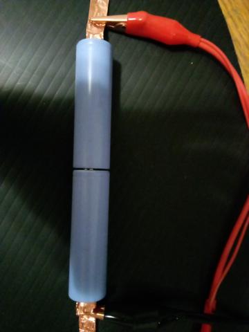
but that is the thinking behind this, something easy that doesnt need any special tools and readily available on the cheap anywhere.
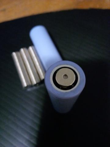
btw, i really like the plasti-dip, all my packs are plasti dipped, the stuff is awesome.
 
going to test the magnets as series connections

L8iRGAZ.jpg


CSBxhh0.jpg


7.5 amp discharge from 8.4v to 6.2v

jNqtVdy.png


Rxitb4I.jpg


temp reached 90f but was dropping right away

ktYpPpX.jpg


im going to test with tape on 1 side of magnet to see how the conductive adhesive affects capacity

VOul3uh.jpg


its no good, resistance of conductive adhesive is too great at 7.5amps and the temperature of the magnet was 6f higher than normal so stopped at 6.7v

JLzUb3z.png


UbUvx9i.jpg


and then with the tape folded 1 time

KJHDyTY.jpg


toaWw6X.jpg


rv5u30R.jpg


Kd80SxR.png


o51AZum.jpg


just the magnet 3095mah
1 side taped doesnt work
folded tape 3105mah

earlier in this thread TheBeastie used copper foil (no conductive adhesive) and magnets with no problems

https://endless-sphere.com/forums/viewtopic.php?f=14&t=106190#p1556575
 
got some salvaged 30Q-136 where the spotwelds were really bad/weak, should be able to clean them with a sanding drum and use magnets

made a 1s70p and slug taped them together to equalize the voltages for a week then take it apart and build 17s4p

IMG_20210222_194148.jpg

IMG_20210222_193943.jpg

IMG_20210222_194126.jpg
 
Now we are talking. This is what I personally have been waiting for in this thread. i.e.- a higher power capacity/maximum safe amperage test from someone that knows how to do it.

I was really impressed by the NESE video that showed very high amp discharge continuous on a paint shaker to show its resilience against vibrations but I don't have a 3D printer or a friend with one. I have a few toys that I would like to slap in a battery that takes a little less investment if at all possible.
 
I'd like to make a note about this, great stuff.

The positive end of 18650 and 21700 cells are very robust and can take quite a bit of abuse when considering various methods of bus connections, such as spot-welding, soldering, and others.

However the negative end is sensitive to heat. Using magnets to hold a copper foil against the negative cell end is a very good method to use. Any concerns that might be expressed about this are issues that can be solved.

Thicker foil can handle higher currents, but if it is too stiff it can limit the contact to the cell-end, even with a magnet pressing against it.

Copper can have treatments that stiffen it, so annealing a roll of copper ribbon can make it what's called "dead soft". Annealing is when you heat it up to a certain temperature [edit: several words removed for being incorrect]

If copper ribbon that is soft enough to guarantee conformity to the cell end is not thick enough for the desired amp-load...I would experiment with two layers is thin copper, rather than a single thicker ribbon.

Either way, thanks for posting the pics and data...
 
spinningmagnets said:
Copper can have treatments that stiffen it, so annealing a roll of copper ribbon can make it what's called "dead soft". Annealing is when you heat it up to a certain temperature, and then allow it to cool down very slowly.
Good idea.

I've noticed that the copper sheet I've bought online has had a certain "springyness" to it (that's the technical term...). Almost certainly due to the cold working during rolling. Annealing would bring down the yield point and definitely help with malleability.

FYI, when annealing copper you can quench it rapidly after heating (like in a bucket of water, under a tap, etc). No need to cool slowly like with ferrous metals.
 
1/4 inch tinned copper braid i think can handle 30amps
wouldnt be hard to slide a magnet inside it

5133R1EeHaL._AC_SX425_ (1).jpg

https://www.amazon.com/Tinned-Copper-Braided-Sleeving-Diameter/dp/B01BIBQCD8
 
goatman said:
got some salvaged 30Q-136 where the spotwelds were really bad/weak, should be able to clean them with a sanding drum and use magnets

made a 1s70p and slug taped them together to equalize the voltages for a week then take it apart ....... and build 17s4p
What kind of test did you do before (.......) assembling your seventy 1s70p 30Q-136 cells and/or after (equalizing the voltages) to determine how many 30Q-136 cells out of the 70 suffer from moderate to high self-discharge?

OR is your plan to hopefully "fix" any 30Q-136 cells suffering from self-discharge only after your 17s4p assembly and not before your 17s4p assembly ?
age7.jpg

So far there seems to be a consensus from other 30Q threads (besides my UPDATE) that 30Q-136/141 cells suffering from self-discharge does not diminish its storage capacity or increase its DCIR.

Will you share your testing method for determining how many of the following 30Q-136 cells in this pack you determined were predisposed to moderate and high self-discharge?
file.php
 
those cells came from a hot glue pack that didnt stick, had bad spot welds the voltages were between 3.58 to 3.28 and is sitting at 3.50v right now. ill explain what im doing in the desulfate 30Q thread

https://endless-sphere.com/forums/viewtopic.php?f=14&t=109601

ill show some of what ill be testing for low amp, slug tape and smaller magnets for a 17s50p-50ampmax pack
just going to do the 30Q first

ill stick the test here for now so i dont cross contaminate/confuse the threads

if i try to charge 1s5p at 3amps diagonally through the pack

IMG_20210223_084854.jpg

the conductive adhesive screws the connection

AX4VYR8.png


and temps rise to 86f, so i clck on the magnets

IMG_20210223_093737.jpg

connections back and temps drop to 78f

T7etIhi.png
 
bought a nickel plated copper ground strap from NAPA part #770-6119 its about 8mm wide
its too thick for the magnets to hold strongly

IMG_20210225_170809.jpg


i opened it up with a screw driver and you can slide the magnets inside, ill be soldering 2 battery leads in between 1p/2p and 3p/4p so i made an opening in the middle so i can slide the magnets in after soldering

IMG_20210225_170905.jpg

IMG_20210225_171646.jpg

holds the weight

IMG_20210225_172008.jpg

going to test nickel plated steel guitar string for parallel connections

IMG_20210225_172121.jpg

IMG_20210225_172239.jpg

do a 90 to solder the bms wires

IMG_20210225_172513.jpg
 
these magnets are 1/4"wide x 1/8" thick

IMG_20210227_130846.jpg

IMG_20210227_130938.jpg

i soldered 1 lead through the center and 1 on top

IMG_20210227_132836.jpg

slip the magnets in and solder the ends

IMG_20210227_135619.jpg

IMG_20210227_140858.jpg

IMG_20210227_140917.jpg

guitar string is easily soldered and strong

IMG_20210227_122908.jpg

measured operating temperature at different amps at a bit more than 1inch

1amp is 80f
2amp is 98f
2.5amp-108f

charging temps
0.5 amps- 76f
1.0 amps- 78f
1.5 amp-82f

IMG_20210227_213015.jpg
 
10mm magnets work fine for 21700 and 26650 batteries but 18650 the positive button is 8mm-diameter and 10mm width is a bit too wide for the cell holders

i figured the copper tape is 0.04mm and the distance between cells is only 1/2 inch, i wanted to do a test before ordering more magnets. the magnets i wound up ordering after this test are 7.5mmx2.5mmx1mm
https://www.indigoinstruments.com/magnets/rare_earth/rings/thin-nd-ring-magnet-7.5x2.5x1mm.html

IMG_20210228_125517.jpg

IMG_20210228_124621.jpg

these are 1/4" compared to 10mm

IMG_20210228_130550.jpg

at 15amp discharge the curve looks fine

egEpwKq.png

i wanted to try using the slug tape instead of braided wire for terminals

fold like this

IMG_20210228_150420.jpg

tape it to itself

IMG_20210228_150902.jpg

solder leads into the center with magnets inside or ontop

IMG_20210228_160040.jpg

IMG_20210228_160344.jpg

checked it at 15 amps

IMG_20210228_155223.jpg

curves fine

UGegrUO.png

i dont think it will be difficult to turn 0.1mm x 30mm soft copper like this

https://www.amazon.ca/YHcXm-Copper-Flashing-Length-Thickness/dp/B085W1Y9DF/ref=sr_1_32?dchild=1&keywords=0.1mm+copper+roll&qid=1614570594&sr=8-32

into this for testing

download (4).jpg
 
the 7.5mm magnets came in

i set the gap at 12.5mm and mark the polarity of the magnets

IMG_20210302_175535.jpg

fold it over twice and mark the seam up

IMG_20210302_180142.jpg

IMG_20210302_204011.jpg

have some 0.1mm copper coming i plan to cut the center in an X and fold it back on itself and use the 10mm magnets, i dont think 7.5mm would hold strong enough

IMG_20210302_204059.jpg

i picked up a load tester like in this video but i need to find a LVC shut off for 72v

https://youtu.be/toDM8_fDx_w?t=386

IMG_20210303_124834.jpg

IMG_20210303_125317.jpg

IMG_20210303_133843.jpg

i need to find some 0.1mm copper locally so i can use it to do the battery terminations like this

IMG_20210303_152547.jpg

IMG_20210303_152554.jpg

IMG_20210303_153405.jpg

IMG_20210303_154020.jpg

IMG_20210303_154342.jpg

IMG_20210303_154618.jpg

IMG_20210303_162733.jpg

wanted to get a coat of plastidip on before something metal gets sucked on the pack and shorting out

IMG_20210303_180803.jpg
 
trying smaller magnets for lower amps
these are 5mm od x 2.5mm id x 1mm thick

#1 is 8mm wide tape, adhesive down, magnet on top
#2 is 16mm wide folded back on itself, magnet on top
#3 is 17mm wide wrapped around magnet

IMG_20210303_185630.jpg

IMG_20210303_190717.jpg

5amp discharge, magnet #1

starting temp 75f, copper slug tape reached 83f after 5 minutes, 86f@10 minutes
battery temp was 94f

kWqOX3a.png

5amp discharge, magnet #2
starting temp 77f, 83f after 5 minutes, 86f@10 minutes
battery temp 92f

EWTCCkr.png

5amp discharge, magnet #3
starting temp 76f, 81f after 5 minutes, 84 f@10 minutes
battery temp 91f

JsQzLNg.png

i wanted to see the discharge curve of a single cell (4.2v) instead of 2s1p (8.4v)

10amp discharge- magnet #3

LJmo1KC.png

battery reached 107f, no scratchiness in discharge curve

n4XiOa7.png

the magnet held strong with an alligator clip hanging off it for the test

IMG_20210303_215644.jpg
 
Do you have any idea how long the 10mm magnets hold their "strength" ? I understand that they are supposed to lose very little for like a hundred years normally, but does current passing through them change that ?
 
Back
Top