48/72V Brushless controller wiring diagram? *Please help*

trophix

10 mW
Joined
Dec 12, 2018
Messages
23
Hey everyone,

I'm sorry if this question has been answered before but I'm new here and I'm trying to upgrade my controller for faster speed.

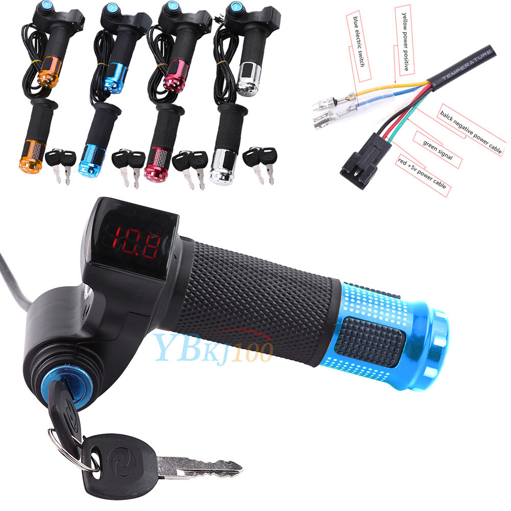
I have an ebike 48/72v controller that I bought from Ebay and I'm having trouble connecting it to my ebike. I connected the power cables(black and red) to the battery, motor wires(blue,green,yellow) to motor as well as the hall cables(5 wires) to the hall cables on the motor. Now I'm just having trouble connecting the rest of the wires on the controller especially the throttle wires. My throttle has 5 wires(Red,Black,Green,Blue,Yellow) but the throttle wire on the controller has only 3. I'd really appreciate the help.

This is the controller I bought....
s-l1600.jpg


And this is the throttle I bought...
s-l1600.jpg


Thank you
 
Hi Trophix,

After you verify :!: that the controllers throttle wires are Red-5vdc Black-0vdc (ground) and what looks to be blue for the sensor wire. I would think they would connect as follows...

The 3 throttle hall sensor wires (black connector) to controller 3 wire (white connector)... Red to Red, Black to Black, and Green to Blue.

The single Yellow would go to battery +.

The single blue wire would go to the E-door lock cable which I think to be the "ignition cable". (verify first) :!:


For more information on hall sensor throttles see this...


Regards,
T.C.
 
Hey Tommy! Thanks for replying back...

.... so should I still try your way?
 
Ok I’ll give that a try. What should I do than with the thin power cable black and red wire?
 
Hey I switched the wires and it worked! Now what what do I do with the rest of the wires on the controller? I have 2 brake handles with 2 wires each... how do I hook them up to the controller?

Thank you again I appreciate you helping me.😊
 
Your welcome, glad you got it going!

Both your brake wire pairs need to be wired in parallel with your low E-Brake controller connection wires. If each of your Brake switch wires are Red and Black... then tie all three Red wires together, and all three Black wires together.

The Low E-brakes is a low voltage (5vdc) low amperage electronic circuit that is actuated by connecting the wires going to the E-brake connector together.
Each hand brake contains a Normally Open switch which closes on brake operation. So when either brake is applied, the switch closes the circuit, actuating the E-brake. This should disable the power to the motor, and if the controller supports it, can enable regeneration.
 
Got it, thank you Tom!

I just MAX'd out my bike speed to 44mph by overvolting the 48v 1000w motor and 72v 1500w 42a controller with a 96v 10ah lipo battery. Is there a way I can get 50mph? Do I need a bigger battery or bigger controller with more amps?
 
Great news, glad to help!

The missing pieces to the speed question would be...
What amperage is your motor drawing now at WOT under full load? And what continuous amperage discharge is your battery/BMS rated at?

Yikes, 20 mph is fast enough for me! :lol:
 
Question I've got a 500 watt 30 amp 48 to 64 volt controller I got used ,wires cut are the striped wires for the hall or the display I'm only a couple years in to this and I'm old so be gental.thank you also trouble with 48 to 86 volt can't get to move.
 
Question I've got a 500 watt 30 amp 48 to 64 volt controller I got used ,wires cut are the striped wires for the hall or the display I'm only a couple years in to this and I'm old so be gental.thank you also trouble with 48 to 86 volt can't get to move.
What specifically did you need to know?

Which specific wires do you have on the controller?

Which of those wires do you already have connected, and to which specific wires on what other parts of your system, and what do those specific wires on those devices do?

Pictures of exactly what you have there, showing the specific wiring you already have, may help us help you as well.

Notes:

Wire colors don't necessarily mean anything at all, as there aren't any obeyed standards.

Displays and controllers are not generally intercompatible, so if the display and controller didn't come as a kit from the manufacturer, they probably won't work together.

A 30A controller should be capable of more than 500w; normally at even 48v these would be called 48 x 30 = 1500w. I suspect there's a digit missing or obscured on your controller label. (so there may be other things missing as well).

If the 64v is a nominal highest-voltage-limit, then that would be for an "18s" pack, and that should mean the max full voltage is around 74v. 86v would be too high a voltage for that, so although it may not damage the controller (it's parts are probably good for 100v if they're good for 74), it may have a cutoff at which point it refuses to operate (HVC).
 
Back
Top