I have question X about my controller.
Well read the FAQ, it will guide you through the basics of this controller. This FAQ is compiled from the collective knowledge of many members (A belated apology for not citing individual contributors: sorry there were just too many!), if you have something to add please pm me or comment on the thread.
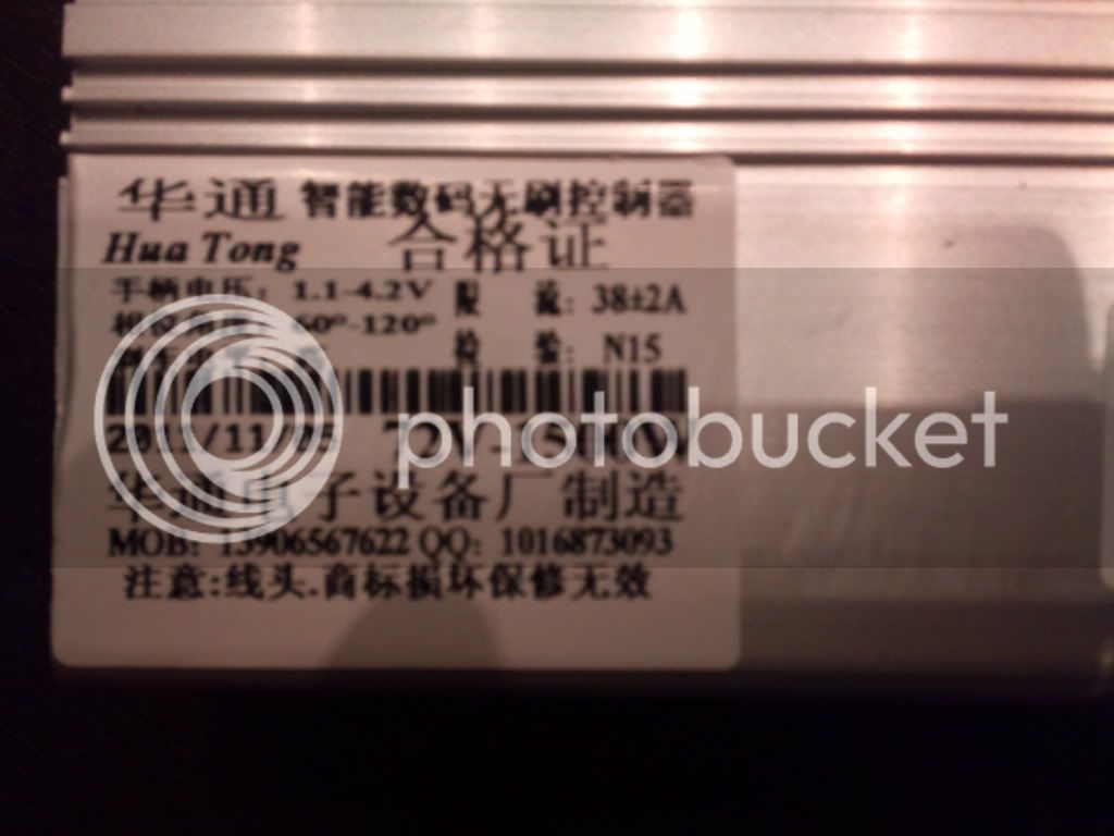
Well what is this Hua Tong OT100?
That is the generic seller name for an expansive series of controllers built by Hua Tong/Ranton manufacturing. The majority of members bought their controllers for ~3X.XX USD from
dhgate or
alibaba. They also sell for 5X.XX USD on
eBay.
Why is the cost so low?
Well primarily due to the miracle of chinese manufacturing. The downside is that you have no idea what you are getting. Explained further later.
What is this constant talk about different boards and dates of manufacturing?
Despite the outwards appearance of the controller. The internals of the controller can vary drastically. The best way to find out what board you have is to peek inside and look for the silkscreen'ed series name.
CA08 XM06AD_P04.1 is the first known iteration of the board. There have been 3 other iterations since (
2nd Generation, C-D3.1, and C-D4.1)
The first generation and second generation boards were broadly similar. Assumed cost saving measures at manufacturing lead to the second generation using the
IRFB4710 mosfets.
The third generation was a extreme departure from the first 2 generations.
A new cpu and additional pads were added to the board.
Fourth generation (need more information)
How many MOSFETs are there?
The 72V version has 15 mosfets.
What type of MOSFETs are used?
CA08 XM06AD_P04.1 board
IRFB4410 Mosfets were used
In later revisions of the board
IRFB4710 Mosfets were used
Can this board be run without hall sensors / sensorless mode?
This board can not be run in sensorless mode.
What features does this board have?
Many of the boards features are only accessible by opening the controller and grounding pads to activate features
List of pads (First and Second Generation):
'X' is wheel lock in later versions, regen in the CA08 XM06AD_P04.1
'L' is reverse
'M2' is low speed**
'DS' 'SL' kill switch
'Q' is for cruise control
'SD' is disable motor (low speed) ?
'SL' is Low brake
'ZL' - 1:1 help ?
*please note that the pad names change between revisions
** only the 3rd generation has a three speed switch
Pads for the C-D3.1
Functions 1-8: need help
How do I turn it on?
Connect the small red wire to V+ (pack positive). This provides power to the low voltage section of the board
Is there a HVC?
No, there is not. Usually, over voltage situations lead to blown mosfets and gate drivers. Use higher voltage with caution.
Then what is the highest voltage that I can run?
The mosfets and capacitors are rated at 100V. As such, many members have reported success with voltages at or slightly higher than 100V. Many believe that 22S ~92V is optimal as it allows for regen and is safer for the mosfets.
LVC?
~60V. It is
easily modifiable.
Is there Regen?
Pack Voltage must be under <90V, so 22S is optimal.
I've never actually run regen could someone cover this?
How do i raise or lower the peak amperage?
To raise the peak amperage, add additional solder to the shunts (3 exposed, silver, [thick] wires on the top left of the board). To decrease the peak, remove parts of the shunt by cutting or grinding or an entire wire from the shunt for a large percentage drop.
What is the peak wattage that I can run?
This depends on a lot of factors that can't all be covered in this FAQ. I personally run a slow wind motor on a large diameter wheel at peak power levels close to 6kW. I've also blown up my board lots of times. I doubt that you could push much more wattage through the board with any reliability.
Does it have programming ability?
Definitly no to the programming. Although there has been a programming header in every revision of the controller you would need to know the cpu and be able to dump the firmware, not to mention figure out the machine code.
Will it run my motor?
If your motor is a brushless 3 phase motor then
yes!
Is there a Cycle Analyst plug.
Nope. A member has been able to create a
custom CA plug
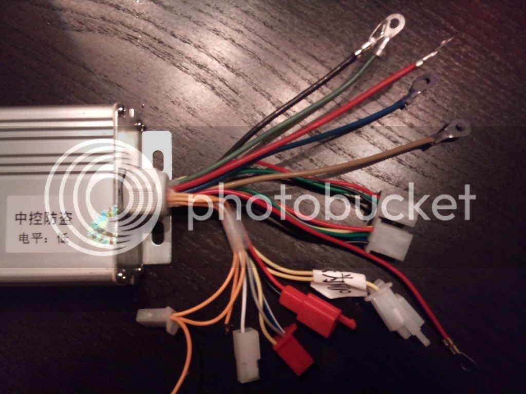
What are all the plugs? I did not receive documentation.
First, Second and Fourth Generation Plugs.
Alarm
(4 pin, 3 populated): One wire has 5v, another has your battery + voltage, and the third is ground. Use it for a voltmeter if you'd like
Hall Sensor
(6 pin, 5 populated) Black: Gnd, Red: 5V, Yellow/Green/Blue: Sensor Output corresponding to Phase
Throttle
(3 pin): Warning! – Wires in connector may be reversed.
Black: Gnd, Red: 5V, Green: Hall output (0-5V)
60/120 wires
(2 pin): Auto its 60, if your motor runs weird, try 120 by connecting the two wires together. If you don't need them connected, simply snip them away.
Ignition: This can either be wired to a switch, that goes to your power supply +, or you can connect it directly to power supply + if you wish to have no switch for ignition.
Voltmeter
(2 pin): This is simply wires that tell you how much battery/pack voltage you have, so you can lead these to a voltmeter if you want, or snip them away. Another use of the voltmeter wires is a DC-DC converter so you can run your aux lights/fans.
Black: Gnd, Red: Pack/Battery Voltage
Third Generation. Additional plugs only
3 Speed
(3 pin): use a SPCO switch. (only on the C-D3.1)
Reverse
(2 pin): Gnd to put the bike in reverse
Black: Gnd, Green: Reverse (only on the C-D3.1)
*only on the C-D3.1
Cruise Control: Wire a momentary switch to it, and lead it to ground. When pressed, cruise control is enabled.
Controller not working?
Blink codes
1 flash: Standby, motor stopped
2 flashes: Throttle input fault or HV brake active
3 flashes: Locked rotor (start speed protection)
4 flashes:
5 flashes: High side FET shorted
6 flashes: Hall sensor fault
7 flashes:
8 flashes: Under voltage (LVC) active
Precharge
I personally use about ~200 ohms as my resistance figure.
This website provides detailed information and a pre-charge calculator

 .
.