A Bad day for me! (my controller repair evolution)

Doctorbass

100 GW
Joined
Apr 8, 2007
Messages
7,500
Location
Quebec, Canada East
Well.. I think a picture would explain you what it happen :( ...

From now, that was a great.... and quick fun...

RRRRrrrrr!?&?/?&/(*? !!! ! ! ! ! ! {N×// hhhhhrrRR!!!!!!!!!!....

:? I'M very disapointed about me!!!... I was so stupid and I forgot something very important!!

Doc
 

Attachments

  • P1020026.jpg
    P1020026.jpg
    22 KB · Views: 3,793
  • P1020024.jpg
    P1020024.jpg
    45.2 KB · Views: 3,792
  • P1020033.jpg
    P1020033.jpg
    27.9 KB · Views: 3,792
  • P1020022.jpg
    P1020022.jpg
    63.3 KB · Views: 3,793
  • P1020034.jpg
    P1020034.jpg
    41 KB · Views: 3,792
Looking on the bright side, you can fit some nice new 150V silicon.

:D
 
Yep, I hate it when that happens.

Probably took out some gate driver chips too.

Time for some 4110's. With those babys, something else will blow instead of the silicon.
 
Hummm.. I really think i can't lcomplete that subject like that without giving an explanation :|

This afternoon, i friend of myne come to see me at my house. After few minutes discussing, I decides to show to him what my new E-bike look's like.

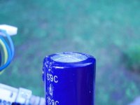
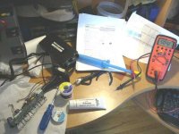
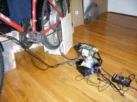
I disconnected my battery from my charger see below:

This charger push the voltage to 90V total in my battery pack.. I charge them for 2 hours to equalize them and drop the voltage to 14.4 for the rest of time.

What happened (maybe!..) is that forgot to leave the battery free of cahrging for few minuts to allow the voltage to stabilyze and decrease to around 82-83V nominal.

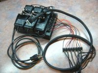
I immediatly took my battery pack and plugged it on the controller :roll: .. I dont remember if the switch was on or off on it... but it happenned in the past without problem.

Immediatly when I plugged the 50A Anderson connector it makes a spark.. a bit louder than normally.. I assume that the caps inside charge faster ands does a peak current... BUT.. that was louder this time...

The Drainbrain become powered and it was ready to operate... ha haaa.. i decided to show to my friend what look like the torque the motor have by just twisting the throttle to the mid position few time and to see the bike moving quickly and pushing with my front weel my toolcase on the ground....

That occured but only for 2 second... and after that my drainbrain shoted down and My fuse (a 40A 32V :... 32Volt :lol:... burned.... eeee... VAPORISED :shock: and leaved a black powder inside the fuse cover(probably the short flame or.. PLASMA! generated)

Well.. .I tried to replace my fuse by another.... and the same thing happened BUT this time i also heard a clic in the controller...

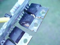
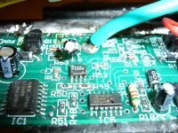
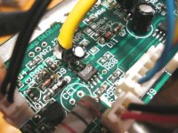
WTF!!.. I immediatly think about the Fets... those ?%?%?$ kind of transistor.. (you just watch them and they blow!!!)...

I smells no smoke from the controller because of the silicone that i corectly put on all the joins.


And finally.........., i'm here... without any possibility of still having fun with my new ebike....

What i think...

-for sure, that was not a good ides to immediatly plug the battery on the controller with a high voltage and avoiding those to stabilyze to their nominal voltage! maybe the controller is a 72V with 100V fets, but probably a little bit borderline taking acount od the pwn that oscillate and generate high volts spike when "3 phasing" and modulating the pwm..


-My second point is that the spark that the anderson connector do each time I plug the battery is certainly bad, because generating spike and hf-hv pulse in some inductive circuit like a hub motor in seri with fets... maybe some caps are too "slow" and leave passing thru the circuit this hv..

-My last point is that i seen that my drain brain was factory preset to 50A max and i decided to leave it to that value.... :roll: ... I can't stop repeting to me : "why i did not set it to the 35A nominal current it is supposed to have!!"... i'm stupid for that too!.. ha ha... no.. i preferes to have fun with acceleration and to post some recorded A peak like 42A.... :roll:

I regrett that!.. why i did that!!!

is it me.... is it the responsability to the seller of the controller to forget seting it to 35A limit... (it's V2 of the drainbrain.. no shunt to modify... it's too easy to make your own adjustment and puting it up to 99A !! :eek:

I repeat.. you could have the bad luck i had!... 35A.. i really think it should stay 35A no more... :x


I've carefully reed some post about controller repair/mod here. they are pretty interesting and i better understant how this controller operate.

I seen you Fechter that have an excelent understanding about this controller and 29A and Xyster i think.

For sure, i want to repair it!!! :D and i want to make it bulledproof!


Now i would appreciate any help from you guys.. .and as i can... i will give you my best for any help you need that i have a great hability in.


Doc
 

Attachments

  • P1020035.jpg
    P1020035.jpg
    55 KB · Views: 3,775
First, I have some important questions:

1-What is the best fet I can buy that have a good price and performance .. at least better than the oem.

2-I seen in the post you did that NORMALLY, we just need to replace:

- the defective fets
- the corresponding fets driver IC (IR2101)
- the corresponding gate resistor (10 ohm smt)

And it should work again WITHOUT blowing on the first test???..

My experience with fets aree BAD :lol: .. each time i tried to replace some in car audio amp, theo blowed again when applying the current...

I hate some switching powerr supply with their many feedback tha make the troubleshooting alot harder!!!

Sincerly guy, i have doubt that it could be only those component that blowed...
-seeing the 2 of 3 160V caps top like that,
-ALL fet blowed... ALL!
-some gate resistor have their 10ohm... only 4 have 57ohm..


I really wonder what could happen if i replace only that... i am no sure it could be ok and simply work well...

Do you think some driver can short and let the current passing to some of the 2 to-92 transistor per phase and blowing them?... or blowing the pwm IC or any other?

And yes, the yellow phase wire is short with the power rail.. to the negative and to the positive!

all i need is that i replace what i should and not blowing them another time!.. i would die...

Can you please guy help me with my questionning?

:wink:

Doc
 
Are you sure you didn't accidently connect the battery reversed? That's usually what blows up everything like that. The caps should not be stressed so much as to bulge out from a very brief current.

Anyway, the stock FETs are garbage and needed to be repalced anyway.

I highly recommend IRFB4110's. If that's too expensive, then IRFB4310's would be next best. Lowell is running them over the voltage limit with no failures yet.

The TO-92 gate high side drivers look blown in the picture. Those will probably need replacing. The IR2101 driver chip might survive sometimes. It's a pain to replace too, so I would test first before replacing.

Testing is tricky, since it won't do anything without an active hall signal input. One way is to connect only the hall wires and the battery, and spin the wheel by hand to rotate the hall signals.

It's also good to test with a current limited power supply instead of the battery. If your battery is the only option, use a small fuse first and run with the wheel off the ground.

I posted a schematic of a safety precharging circuit somewhere. This eliminates the big spark when you connect the batteries. It also prevents you from closing the relay if the FETs are shorted.
 
Yes fechter, i had alerady pluged bi accident the battery reversed, BUT.. that was'nt that time.. it was 4 days ago!.. The controler worked pretty well.. no apparent damage.. i got a peak current of 39A without any trouble. I went to my job without problem...

I also had a 40A fuse that protected it. it blowed eee.. VAPORIZED..., i replaced it and it worked without any problem for the rest of the day.

Do you think that could partially damaged the fets or any other component around and increassed the risk of blowing up some?

I really dont understant why the caps are bulge like that (2 out of 3).. i agree, i would be surprized if a brief reversed current could produce that!
I will test those... and to be sure no leakage current and that their valur is at least 220uF.

I wonder how far the blast hit some component.. starting from the fets, to the gate driver..to the fet driver, to the pwm?... to the thiny to92?

hum.. a new controller is 190$... i wonder finally how much could it cost me to completly repair it and to be sure it will not blow up again!

I HATE TO REPAIR FETS CIRCUITS!.. when you power up it again you see your entire life in your brain in the few millisecond after power is applied!

Doc
 
u are now
Dr. BassAckwards :lol:
 
4110's were around $4.28ea, times 12 would be a bit over $50us.
The other parts are very cheap. Apparently you can order them directly from International Rectifier. I got mine from DigiKey, but they tend to run out of stock.

I've not seen the PWM or commutator chip fail, but anything's possible.

It's possible that one FET bank blew when you reversed it, but the others were still working enough to run the motor for a while.

After repairing, you can test at reduced voltage. I have a bench power supply that only goes to 30v, but that's perfect for testing. Something with a current limiter you can set very low is great for testing. With the phase wires disconnected, everything else will only draw about 0.1 amps.

Alternately, you could place a resistor in series with the battery that will limit the current into a dead short to under 1 amp. A light bulb is great for this.

To fix a really toasted one like yours, you should really use an oscilloscope to make sure all the gate drive signals are good. A good DVM with a fast reading min/max memory might work OK too.

Once all the gate drives are good, it should be pretty bulletproof up to 60-70 amps and 100v.

One more idea: remove all the fried silicon and try to test the ouput of the gate drivers before installing new FETs. If your PWM or commutator chip failed, it may not be worth repairing. With no FETs installed, there is little chance of blowing anything else.
 
I have a contact here from Electronic depot that buy batch of component at high volume price. he will place an order friday. i think i will not take any chance to miss or forget some component . I would order:

IR2101 6x 1.92$ @ Newark (16F9225 )

IRFB4110PBF 12x 4.50$us Arrownac

2N5551 6x 0.15$us @Newark(45J2499 )
2N5401 6x 0.15$us @Newark (45J2495 )

UPC1246C 2x price? where to buy?

10r smt resist 24x


Some component will be doubled quantity... i prefer to have spares!


Tonight I will test all the board to see exactly what is blown and I would place my order tomorrow fonction as what component I found that are blown.

Doc
 
You should have it covered!

I wouldn't worry about the uPC1246 unless you have reason to believe it's damaged. I've never heard of one failing.
 
Tonight I removed all fets.. it took me around 45min.

I put a small regularised power supply 1 A max 36V and the red led was ok, but the controller was pulling 570mA.... 4 sec later, a Triple 3-input AND gate IC blown (the hef4073b)... and the IR2101 seems to be blown too...
 

Attachments

  • P1020049.jpg
    P1020049.jpg
    62.5 KB · Views: 3,641
  • P1020053.jpg
    P1020053.jpg
    52 KB · Views: 3,639
  • P1020055.jpg
    P1020055.jpg
    59.2 KB · Views: 3,639
  • P1020056.jpg
    P1020056.jpg
    48.3 KB · Views: 3,641
  • P1020043.jpg
    P1020043.jpg
    51.8 KB · Views: 3,639
Well it's not a total disaster, but manu IC suffered....

The Q1, (2n5551) small to-92 is blown and the Q2(13005A) to-220 near the 2W resistor is blown too (it have the base-emetter completly shorted. Probably they provide lower voltage thru the big 2W resistor and my 36 Volt may have goes to the HEF 4073 Triple 3-input AND gate IC and is responsible to blown it.


BUT.. i removed those carefully all those that flollow

-12x 4710 fets blown
-3x ir2101 blown
-4x 10r smt resistor blown
-1x Hef4073 IC blown
-1x 13005A transistor to-220 blown
-1x 2N5551 transistor to-92 blown


:shock:

I tried to power up the system and YESS!!! no more than 7mA at 36V!!!

After removing half of the semiconductor on this board.. incridibble noh?!! :?

the drain brain seems to work very well. I was curious to see what was the last recorded data like max current, min volts.. etc.. and i am surprized!

Min volt 32.9V
Max current 32A... only 32 and it blown????????????

hummm...... does it could be a manufacture responsability? only 32A...

If i remember correctly, the voltage i've read last time i connected the battery(just few second before it blown, was 82.9V)... that's under the max allowed 87V like in the article of Crystalyte website...

I begin to suspect it could be not me the full responsible of that..

82.9V at 32A and it blown immesiatly when i connected it to the battery...

Anyway.. i've already begin to repair it.. but it will take much more time than i expected.. many IC, transistor are blown

I will post any developpment about this saga...

now i need to sleep.. it's late here

Doc
 
That one really blew up. Reverse polarity to the battery will destroy most controllers. They have no protection against this. Almost anything can go with reverse polarity.

Your test setup looks great. Good luck on replacing the parts.
I used solder wick on the IR2101's to get the legs free. I also lifted a trace off the board in the process, but made a small jumper wire to replace it.

If the voltage regulator transistor shorted, the full battery voltage would be applied to parts that are only made to take 15v.

Since your idle current looks good, you can probably assume the fried silicon is gone. You might need to check around for blown resistors.
 
What is strange in all that, is that after i reversed the polarity, it worked well for 2 or 3 runs... it blown just the next day when I reconnected the charged battery....

I wonder if puting a caps and diode in parallel to the Anderson connector of the power connector would help prevent spark.. because i think that could be the spark when i connect the battery too..

Changing alot of blown resistors, and a majority of IC, trtansistor would cost me the price of a new controller maybe... but i wonder if Justine would send me just a main board..?


Doc
 
You deserve a medal for the worst controller ever blown on this forum. And, if you get it to run again, you should get another medal. Good luck. I would have bought another one. :D
 
D-Man said:
And, if you get it to run again, you should get another medal. Good luck. I would have bought another one. :D

I keep confident! :wink:


--tonight I got my 5V from the regulator... it was the pin 15 of the PWM ka3525 that has a problem. that' the Vcc of this IC.. i simply cutted it close to the board to see if it was this that cause the voltage to stay at 3.2V... then after, it goes to 5.06V!!!

1 problem out of 1000 solved!


From now

-the two lm358 op are ok
-the 1246 seems to be of... no voltage drop
-the 78L05 was ok
-the 2n5551 and 2n 5401 are ok too

The draw current is less than 10mA at 36V with the red led that glow.

BUT I dont have my 12V.. I have only 8V.. I'm trying to understand how this curcuit part is working to start from the V+ to drop to 12V (now 8V)

I seen the 13005A transistor around thge big 3k resistor and it seems to be around this... the 3k resistor have the V+ on one lead and 8V on the other

Doc
 
I think there's a zener diode that works with the regulator transistor to provide the ~14v for much of the circuitry. On the regulator transistor, you should have battery voltage on the collector, and about 14v on the emitter. I guess that would mean around 15v on the base, which is determined by the zener diode.

I'm kinda guessing here, since I haven't traced out that part of the circuit before.
 
Yesterday I've tried to replace that zener diode (just below the 3kohms resistor. I had no 12V or 14V zenner diode so I put 2 in series to get 12V and I got 11.2V from now. I checked the 12V rail and it seems to me ok.

Can you check what is the voltage you get on that "12V" rail for me?
I noticed that this voltage change fonction of the supply current.. probably du to the zener polarizarion slope.

You talk about 14V.. and the schematic indicate 12V.. I dont know if it's very important but I know it should be under 18V due to the upc1246 IC max limit...and the ir2101 max 25V limit.

Doc
 
Doctorbass said:
You talk about 14V.. and the schematic indicate 12V.. I dont know if it's very important but I know it should be under 18V due to the upc1246 IC max limit...and the ir2101 max 25V limit.

Doc

Right. I think it's supposed to be 14v (measured on one), but anywhere between 12v -14v should work fine. This supplies the gate drive voltage as well.
 
Thanks Fechter, your very helpfull! 8)
 
Hi Doc ,
hows the repair going,

was wondering how did you tested these components

the two lm358 op are ok
-the 1246 seems to be of... no voltage drop
-the 78L05 was ok
-the 2n5551 and 2n 5401 are ok too
 
the two lm358 op are ok
-the 1246 seems to be of... no voltage drop
-the 78L05 was ok


-for the 2n5551 and 2n 5401 , i used a multimeter and tested for Vdiode around 0.5 to 0.7V and no short between b c e

-for the 78L05 I tested at pin 3 if i get 5 volt refering to the ground(pin2) and ensure that the V in at pin 1 is around 12 to 15V(it depend on the 13005 transistor and the zener near the big 3W resistor. the zenner should be a 12 or 13V

-for the the 1246 I simply tested the input Vcc (it's the 12V rail that supply all IC) and to be sure that it not short it. (if any Ic short, the 12V rail will drop.
 
Sounds like you're making progress. Sorry I've been a bit busy to really keep up with things.

Someone reported getting IRFB4110s directly from International Rectifier.
 
Back
Top