A Small 6 fet Vesc 6 Design

I have built the second prototype now with the suggested inprovements. I flashed it with the bldc master branch and downloaded the vesc tool from the vesc website but I am getting an error that the vesc has newer firmware than the vesc tool and the vesc has test firmware which isn't a safe situation so limited communication mode is used.
 
You need to switch to the 5.03 release branch, that's all.

Vedder and a few others decided to keep master as the prototype branch, the latest greatest might not quite work est.

The stable release lives in its own branch... Use git checkout _name of branch_
 
Thanks, did that, run a test and no squealing at all. Motor runs silently and smoothly so will need to do a road test soon.
 
So here is my first road test. It works perfectly apart from the regen cutting out for about a second before coming back on again. This only happens during hard regen braking. The motor sometimes doesn't start properly but I think that is because of my loose axles.
[youtube]https://youtu.be/EgfNWWEtfNQ[/youtube]
 
sdobbie said:
So here is my first road test. It works perfectly apart from the regen cutting out for about a second before coming back on again. This only happens during hard regen braking. The motor sometimes doesn't start properly but I think that is because of my loose axles.
[youtube]https://youtu.be/EgfNWWEtfNQ[/youtube]

Congrats dude, looks like it is working ok! Bit noisey... Presume that's a geared hub or something?

Glad to have helped! :bigthumb:
 
sdobbie said:
It's just the hub motor noise. So I can diagnose the regen issue, can I use a hc05 Bluetooth module with the vesc app?

Please try it and let me know the answer there. I've got a few of them and never tried. Just bought a flipsky one that plus into the standard VESC header
 
WOW... I caught the VOD on youtube about the controller, Reading this thread was just epic. I hope the road testing goes well. if there is a pre-order or any way I could help let me know what you might need.
 
sungod1 said:
WOW... I caught the VOD on youtube about the controller, Reading this thread was just epic. I hope the road testing goes well. if there is a pre-order or any way I could help let me know what you might need.

Hi, Help with power stage layout and design would be good, if there's any flaws you might see.
I am going to redesign this controller where the power stage, 12v, 5v and 3.3v power supplies are on the bottom board and the MCU will be on a separate board which plugs in on top. That way I will reduce the price considerably as a 4 layer PCB won't be needed and I will maybe be able to reduce noise and interference as I can keep the analog sensing lines more separate.
 
sdobbie said:
sungod1 said:
WOW... I caught the VOD on youtube about the controller, Reading this thread was just epic. I hope the road testing goes well. if there is a pre-order or any way I could help let me know what you might need.

Hi, Help with power stage layout and design would be good, if there's any flaws you might see.
I am going to redesign this controller where the power stage, 12v, 5v and 3.3v power supplies are on the bottom board and the MCU will be on a separate board which plugs in on top. That way I will reduce the price considerably as a 4 layer PCB won't be needed and I will maybe be able to reduce noise and interference as I can keep the analog sensing lines more separate.
I advise strongly against 2 layer boards for power stuff. The noise you'll suffer by not having a ground plane is simply not worth the effort and cost saving.
 
sdobbie said:
I am going to redesign this controller where the power stage, 12v, 5v and 3.3v power supplies are on the bottom board and the MCU will be on a separate board which plugs in on top. That way I will reduce the price considerably as a 4 layer PCB won't be needed and I will maybe be able to reduce noise and interference as I can keep the analog sensing lines more separate.
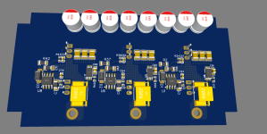
Will you do the same as our EasyDIY ESC, where we use the MCU board Bluepill? -- and we are even plugging one DC-DC board module on top of the other:
3D_TH_Side.png


3D_SMD_Side.png
 
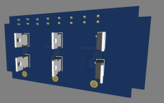
My design will be similar but I am using a totally different set of components and layout. The mosfets will be heatsunk to the bottom of the aluminium box I am mounting this in so they will be bent back against the pcb. I have yet to design the board that goes on top, this is just a rough layout.
Untitled1.png

Untitled2.png
 
Back
Top