
Alright, well it was a good effort. Too bad the inverter gave up! One of those cases where you are testing stuff and everything should be within spec, and it still blew up.. we might never know why. Specially when you are testing new ideas like this, leaves you wondering about it. Im guessing that it was a poor design in the inverter that killed it.
You are using an out of date browser. It may not display this or other websites correctly.
You should upgrade or use an alternative browser.
You should upgrade or use an alternative browser.
Active pre-charge/inrush control
- Thread starter boo
- Start date
regmeister
100 W
- Joined
- May 9, 2009
- Messages
- 264
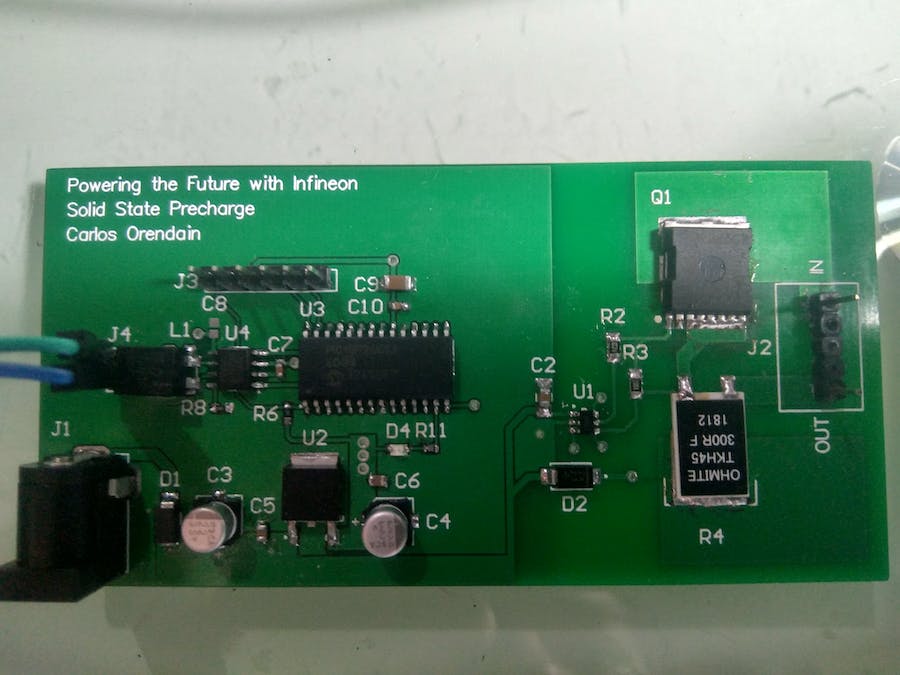
Perhaps someone reading this thread will find interest in this.
In the comments, I read that the project was supposedly the winner of whatever contest they had going on.
Solid State Precharge CoolMOS solution for automotive HV battery.
In the comments, I read that the project was supposedly the winner of whatever contest they had going on.
Solid State Precharge CoolMOS solution for automotive HV battery.
Using CoolMOS the cost will be lower and the physical size too, with better reliability.
regmeister said:Perhaps someone reading this thread will find interest in this.
In the comments, I read that the project was supposedly the winner of whatever contest they had going on.
Solid State Precharge CoolMOS solution for automotive HV battery.
Using CoolMOS the cost will be lower and the physical size too, with better reliability.
If you have a bluetooth bms with a hardware or software on/off switch, the fets can act like solid state relays and cut the power while you plug.
Tommm said:regmeister said:Perhaps someone reading this thread will find interest in this.
In the comments, I read that the project was supposedly the winner of whatever contest they had going on.
Solid State Precharge CoolMOS solution for automotive HV battery.
Using CoolMOS the cost will be lower and the physical size too, with better reliability.
If you have a bluetooth bms with a hardware or software on/off switch, the fets can act like solid state relays and cut the power while you plug.
Reading this, I wonder if that wouldn't just trip the bms short circuit protection/stress the cells instead.
Tommm said:Reading this, I wonder if that wouldn't just trip the bms short circuit protection/stress the cells instead.
If your switch, whatever it is, is trying to suddenly turn on a controller with fully discharged caps, you could blow the FETs. If the FETs are overkill enough, they can probably survive, especially for smaller bike sized controllers. I've seen BMS boards set up to do on/off switching before. Some are picky about not turning on with a zero volt load. It usually takes a precharge resistor to make it work, which also solves the inrush current problem.
rengelking
1 µW
- Joined
- Aug 12, 2019
- Messages
- 2
I re-did the circuit posted on page 5, only it now has a number of improvements:
The voltage divider on the lower left is just to simulate a 3.3V logic level coming from Raspberry Pi or other 3.3V processor:

I was able to build a nice protoboard of it that works great:

- 1. high side P-MOSFET switching; this is important because other circuits could have GND through USB creating a short on low-side circuits
2. plugin current limiting, when power is first connected (the other one gave a huge spike)
3. current limited to 150mA (100mA if using 2.2m Ohm resistor 2.2uF cap)
4. power also controllable by Raspberry Pi 3.3V logic level with LOW normally off
5. able to use electrolytic polarized capacitor (cheaper, easier to find)
The voltage divider on the lower left is just to simulate a 3.3V logic level coming from Raspberry Pi or other 3.3V processor:
I was able to build a nice protoboard of it that works great:
Nice :thumb:
Generally N channel FETs have lower on resistance so you need less of them to handle a given current.
What FETs did you use?
Generally N channel FETs have lower on resistance so you need less of them to handle a given current.
What FETs did you use?
rengelking
1 µW
- Joined
- Aug 12, 2019
- Messages
- 2
Thanks!
The N-Channel is one of these:
WeiMeet RFP30N06LE 30A 60V N-Channel Power Mosfet TO-220 ESD Rated for Arduino
https://www.amazon.com/gp/product/B07CTF1JVD/ref=ppx_yo_dt_b_search_asin_title?ie=UTF8&psc=1
The three P-Channel MOSFETs are the:
Bridgold 10pcs FQP27P06 P-Channel MOSFET, 60V, 27A, TO-220,3-Pin
https://www.amazon.com/gp/product/B07LG3X8KF/ref=ppx_yo_dt_b_search_asin_title?ie=UTF8&psc=1
The on resistance is pretty much zero at 12 volts on the P channel MOSFETs, at least the voltage drop is not detectable according to my multi-meter when it is on.
rengelking said:Thanks!
The three P-Channel MOSFETs are the:
Bridgold 10pcs FQP27P06 P-Channel MOSFET, 60V, 27A, TO-220,3-Pin
https://www.amazon.com/gp/product/B07LG3X8KF/ref=ppx_yo_dt_b_search_asin_title?ie=UTF8&psc=1
Spec says 70mOhm. A N channel like IRFB4110 is closer to 4mOhm, so a big difference. For lower current loads, it won't matter much but if you run 100A controller it makes a huge difference. You can put as many as needed to run your load but it becomes impractical (and expensive) if you need more than about 10.
I am designing a PCB for 6 mosfet version, from 3b version from fetcher. Here comes the board:

What do you think?
In between the mosfet, I left the perfect space for this heatsink (40x25mm version):
https://www.aliexpress.com/item/4001107677711.html?spm=a2g0s.9042311.0.0.5d4d4c4d1fNezv
The 2 pin header is for a battery voltage monitor. The 4 pin header, is for normal switch, plus permanent negative for led. Negative Holes are for 10awg cables.
I am planning to use this on around 100 continuous amps. And I am planning to mount these mosfets:
https://www.mouser.de/datasheet/2/196/irf1324pbf-1228043.pdf
If anyone wants the eagle files, please message me.
Regards
Alan B
100 GW
Might want to check the current handling capacity of the traces.
Alan B
100 GW
10 gauge wire is rated for about 50 amps.
https://www.engineeringtoolbox.com/wire-gauges-d_419.html
https://www.engineeringtoolbox.com/wire-gauges-d_419.html

Alan B
100 GW
Calculate the heat in the wire. 100 amps at 0.17 volts would be 17 watts of heat. If it is really continuous it could get quite hot, depending on the cooling situation.
Alan B said:Calculate the heat in the wire. 100 amps at 0.17 volts would be 17 watts of heat. If it is really continuous it could get quite hot, depending on the cooling situation.
thanks man, will try to squeeze an 8awg, and make those holes with pads slightly bigger. The current to the gates and Zener is minimal right? I mean, less than 1mA probably right?
lqbweb said:thanks man, will try to squeeze an 8awg, and make those holes with pads slightly bigger. The current to the gates and Zener is minimal right? I mean, less than 1mA probably right?
Correct. Those traces can be very skinny.
I have made the layout smaller, and put both negatives to one side and holes for 8awg.

Size: 51.8 x 23.2 mm, smaller than this with 6 fets... and heatsink.... gets complicated.
In between the mosfet, there is enough gap to put a screw, since I am planning with a small plate to press the mosfet rows to each other against the heatsink.
Ordered to OSH! Here the link to my project:
https://oshpark.com/shared_projects/guZp1xNz
Here I also attach the Eagle project, with both layouts.
Thanks guys
Attachments


Otto44 said:I am building this switch right now.
Can I use this capacitor for it?
It is 1µF
Thanks for the help
Toto
Yes, that looks good.
Hello Fechter
thanks for the reply.
Does this circuit consume any current when connected to the battery?
I am thinking of placing it inside my battery box.
I used 6 of the 100v FET‘s you suggested. Placed on a 6mm Aluminium Heat sink around 65x50mm. What do you think it can handle as cont current at 14S battery.
And what happens if I switch it off under load?

Thanks for the help.
Toto
thanks for the reply.
Does this circuit consume any current when connected to the battery?
I am thinking of placing it inside my battery box.
I used 6 of the 100v FET‘s you suggested. Placed on a 6mm Aluminium Heat sink around 65x50mm. What do you think it can handle as cont current at 14S battery.
And what happens if I switch it off under load?
Thanks for the help.
Toto
The circuit consumes zero power when off. It takes a few microamps when on (nearly zero).Otto44 said:Hello Fechter
thanks for the reply.
Does this circuit consume any current when connected to the battery?
I am thinking of placing it inside my battery box.
I used 6 of the 100v FET‘s you suggested. Placed on a 6mm Aluminium Heat sink around 65x50mm. What do you think it can handle as cont current at 14S battery.
And what happens if I switch it off under load?
Thanks for the help.
Toto
Current capacity is limited by heat, so depends on a lot of things. I think you'd be fine up to 100A. Best to check temperature after running it hard for a while. It can tolerate pretty high temps, but you don't want it to get so hot you can't touch it.
No problem switching off under load. The controller main caps will prevent any large voltage spikes.
Did you build this? How is it working?
lqbweb said:I have made the layout smaller, and put both negatives to one side and holes for 8awg.
versionb.png
Size: 51.8 x 23.2 mm, smaller than this with 6 fets... and heatsink.... gets complicated.
In between the mosfet, there is enough gap to put a screw, since I am planning with a small plate to press the mosfet rows to each other against the heatsink.
Ordered to OSH! Here the link to my project:
https://oshpark.com/shared_projects/guZp1xNz
Here I also attach the Eagle project, with both layouts.
Thanks guys
Powervelocity.com
100 kW
I've build the v1 of the circuit (with 2x 1M resistor divider) and a single switch to the high side and that, as expected, kept blowing the mosfets as they often operated in the linear region for a very long time - primarily during turn off as 1M is obviously not enough to pull the gate below 2v (Vgs for these mosfets)
Then I removed the 1uF cap to effectively disable the pre-charge circuit and that helped to turn off the gate instantly but the other issues came up.
The low side of the 1st phase H-Bridge of the controller (farthest away from the battery and the one getting the most DC link capacitance) keeps blowing up mosfets (shorting) pretty consistently approximately within 2 seconds of the turn-on. I could not yet confirm this yet but it seems like switching the battery negative and lots of caps on the DC link cause the low side mosfets of the power stage to exceed their 20v gate limit.
Just wanted to share some experiences and see if anybody had any ideas how to mitigate this.
Similar threads

- Replies
- 8
- Views
- 955
- Replies
- 9
- Views
- 1,843
- Replies
- 25
- Views
- 2,682
- Replies
- 5
- Views
- 3,172