ElectricGod
10 MW
This specific post is for the Astroflight 3220 inrunner.
I have looked around at what others have done to motors that don't have halls and also I have 6 BLDC's with halls. I looked at everything and finally just decided to add halls on top of the teeth. Several of my motors have the halls embedded in the center of the face of three stator teeth. Several have them between the teeth. I've looked at what others did when they added halls and that too was either between the teeth or right in the middle of them. I'm not sure that either position matters or not. My 41F halls were too wide to fit between the teeth and I didn't want to grind slots in the faces of 3 teeth so I just temporarily super glued them to the tops of the teeth and it worked. I tested the halls with my multimeter, a motor hall tester and on two different motor controllers that use halls and the halls worked great every time.
NOTE: I later found out the correct hall placement. Count the number of teeth on the stator. If there is an even number of stator teeth, the halls go at the gaps between the stator teeth. If there is an odd number of stator teeth the halls go in the middle of the stator teeth.
Looking at these pictures, I did it wrong. The halls should be between the stator teeth since this motor has an even number of stator teeth.
Essentially what I did was count the teeth in the motor and then divided 360 by that number to find out how many degrees a single tooth used. Since I wanted 120 degrees between halls, I then divided 120 by the degrees a single tooth took to find out how many teeth should be between halls. In other words every 4th tooth. I arbitrarily picked a tooth that had easy access to it and then counted 4 more teeth and that's where I placed the next hall and then 4 more teeth after that for the next hall. I lightly super glued them in place on top of the teeth so that if I was wrong about placement, I could always break them loose easily to be placed elsewhere. I started to put epoxy on one of the halls and realized I should take pics. Anyway, sorry for messing it up before you could see all 3 halls clearly. Since it all works correctly, they are now epoxied in place.


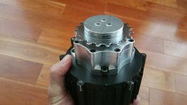
This is the motor all closed up and tested.

I didn't know which hall went with which phase so I arbitrarily used the 3 wire colors and then started trying different hall combinations to find the correct one. Sticking the hall wires into the hall connector on the controller was an easy way to determine the correct combination. It either doesn't work at all and the motor just chugs or stutters or else the combination runs the motor. There's a combination that will run the motor, but it gets hot very quickly despite not being under load. There's the correct combination that works smoothly and the motor doesn't get hot with no load. This is that combination.

I have looked around at what others have done to motors that don't have halls and also I have 6 BLDC's with halls. I looked at everything and finally just decided to add halls on top of the teeth. Several of my motors have the halls embedded in the center of the face of three stator teeth. Several have them between the teeth. I've looked at what others did when they added halls and that too was either between the teeth or right in the middle of them. I'm not sure that either position matters or not. My 41F halls were too wide to fit between the teeth and I didn't want to grind slots in the faces of 3 teeth so I just temporarily super glued them to the tops of the teeth and it worked. I tested the halls with my multimeter, a motor hall tester and on two different motor controllers that use halls and the halls worked great every time.
NOTE: I later found out the correct hall placement. Count the number of teeth on the stator. If there is an even number of stator teeth, the halls go at the gaps between the stator teeth. If there is an odd number of stator teeth the halls go in the middle of the stator teeth.
Looking at these pictures, I did it wrong. The halls should be between the stator teeth since this motor has an even number of stator teeth.
Essentially what I did was count the teeth in the motor and then divided 360 by that number to find out how many degrees a single tooth used. Since I wanted 120 degrees between halls, I then divided 120 by the degrees a single tooth took to find out how many teeth should be between halls. In other words every 4th tooth. I arbitrarily picked a tooth that had easy access to it and then counted 4 more teeth and that's where I placed the next hall and then 4 more teeth after that for the next hall. I lightly super glued them in place on top of the teeth so that if I was wrong about placement, I could always break them loose easily to be placed elsewhere. I started to put epoxy on one of the halls and realized I should take pics. Anyway, sorry for messing it up before you could see all 3 halls clearly. Since it all works correctly, they are now epoxied in place.
This is the motor all closed up and tested.
I didn't know which hall went with which phase so I arbitrarily used the 3 wire colors and then started trying different hall combinations to find the correct one. Sticking the hall wires into the hall connector on the controller was an easy way to determine the correct combination. It either doesn't work at all and the motor just chugs or stutters or else the combination runs the motor. There's a combination that will run the motor, but it gets hot very quickly despite not being under load. There's the correct combination that works smoothly and the motor doesn't get hot with no load. This is that combination.
")