
Kingfish
100 MW
Related Thread: DOT Vehicle Lighting
Greetings
I am preparing to upgrade my ebike to accept a parallel lighting system that enables Motorcycle-style control lighting.
At present, I use a DC-DC converter that takes 33-75 VDC in and has 3.3 & 12 VDC out. The 3.3V is used to run my High-Powered Cree LED flashlights as headlamps, and for driving the flashy red-white Blinkys in the rear. Each unit has their own circuit switch. The 12V channel is unused at present, however in the new schema this will be used to power running lights, signal, brake light, and quite possibly a future horn & central headlamp. I tender two schematics; present and future:

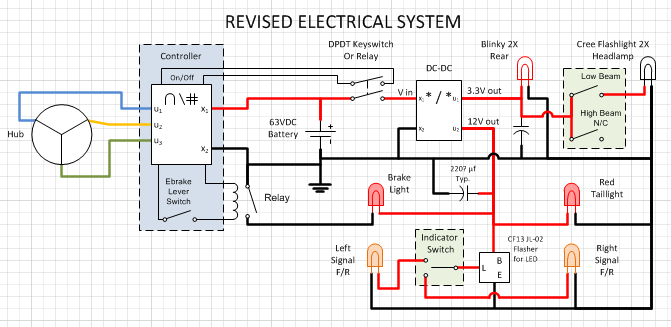
Planned revised system
* Please excuse my lame schematics; I used Visio and the component selections are not the best. The key pieces are that the Controller = Infineon PWM Controller, and DC-DC = the DC-DC Converter previously mentioned.
I think everything else is straight-up.")
The present system works, it’s just cumbersome because the switches are inline and float; there are three total: DC Converter On/Off, Headlight On/Off, and the Controller On/Off (not illustrated).
Present system
The revised system is obviously more complicated. The key features are that I am tapping into the 12V leg of the DC converter to power the automobile-class electricals such as the running lights, brake, and indicators. For the Brake light, I thought of using a simple inline 5VDC relay to close the circuit. However I don’t know if the current drop will overload the PWM controller electronics. The optimum solution would be a DPDT however I have not been able to source a single micro lever switch for cheap. The relay looked like a very inexpensive way to go. Thoughts?
I did source a Flasher for LEDs and this is indicated in the system schematic.
The 12V supply would get an electrolytic capacitor; I’m thinking 220μF would be enough. The whole leg is all low-power LED, and even the flasher is supposed to be solid-state.
Finally, the On/Off power switch to the DC converter would be replaced by a keyswitch, but the one I wish to use is not a DP so again I was thinking either use another inline relay, or bypass the LM317 & R1 business altogether and directly inject conditioned 12V into the controller before the 5V regulator. I think this would simplify the On/Off problem and cut out the pesky trickle-down drain. I don’t know how this would affect the inrush current though.

Motorcycle Handlebar Controls for headlights, Indicators, & Horn
The Low/High Beam and Indicator switches are integrated into a new handlebar controller for motorcycles. At preset the high beam and horn will not be used. To make room, the present 3-way Speed control and Cruise Control module will go from the left to the right side (even though I prefer having Cruise on the left). This will make for a crowded handlebar. To regain needed real estate the gear shifters are being swapped out from Shimano to SRAM Attack.
That’s the Plan anyway. Except for the taillight – all the pieces have arrived. Restating the questions:
DC-DC Converters
Cree HP-LED Conversion & DC-DC Converter Assy
It’s a little bit ambitious, but then so is the whole hobby
Thanks kindly, KF
Greetings
I am preparing to upgrade my ebike to accept a parallel lighting system that enables Motorcycle-style control lighting.
At present, I use a DC-DC converter that takes 33-75 VDC in and has 3.3 & 12 VDC out. The 3.3V is used to run my High-Powered Cree LED flashlights as headlamps, and for driving the flashy red-white Blinkys in the rear. Each unit has their own circuit switch. The 12V channel is unused at present, however in the new schema this will be used to power running lights, signal, brake light, and quite possibly a future horn & central headlamp. I tender two schematics; present and future:
Planned revised system
* Please excuse my lame schematics; I used Visio and the component selections are not the best. The key pieces are that the Controller = Infineon PWM Controller, and DC-DC = the DC-DC Converter previously mentioned.
I think everything else is straight-up.
The present system works, it’s just cumbersome because the switches are inline and float; there are three total: DC Converter On/Off, Headlight On/Off, and the Controller On/Off (not illustrated).
Present system
The revised system is obviously more complicated. The key features are that I am tapping into the 12V leg of the DC converter to power the automobile-class electricals such as the running lights, brake, and indicators. For the Brake light, I thought of using a simple inline 5VDC relay to close the circuit. However I don’t know if the current drop will overload the PWM controller electronics. The optimum solution would be a DPDT however I have not been able to source a single micro lever switch for cheap. The relay looked like a very inexpensive way to go. Thoughts?
I did source a Flasher for LEDs and this is indicated in the system schematic.
The 12V supply would get an electrolytic capacitor; I’m thinking 220μF would be enough. The whole leg is all low-power LED, and even the flasher is supposed to be solid-state.
Finally, the On/Off power switch to the DC converter would be replaced by a keyswitch, but the one I wish to use is not a DP so again I was thinking either use another inline relay, or bypass the LM317 & R1 business altogether and directly inject conditioned 12V into the controller before the 5V regulator. I think this would simplify the On/Off problem and cut out the pesky trickle-down drain. I don’t know how this would affect the inrush current though.
Motorcycle Handlebar Controls for headlights, Indicators, & Horn
The Low/High Beam and Indicator switches are integrated into a new handlebar controller for motorcycles. At preset the high beam and horn will not be used. To make room, the present 3-way Speed control and Cruise Control module will go from the left to the right side (even though I prefer having Cruise on the left). This will make for a crowded handlebar. To regain needed real estate the gear shifters are being swapped out from Shimano to SRAM Attack.
That’s the Plan anyway. Except for the taillight – all the pieces have arrived. Restating the questions:
- Would a 5VDC relay work inline on the Ebrake circuit to complete the Brake-Light? I would be most grateful for a little help speccing one out. The alternative is a DPDT micro/mini lever switch. Presently I have a SPDT from RadioShack and it is doing a bang-up good job well and above the magnetic reed switch.
- Likewise would it be possibly to bypass LM317 with 12VDC from the converter?
DC-DC Converters
Cree HP-LED Conversion & DC-DC Converter Assy
It’s a little bit ambitious, but then so is the whole hobby
Thanks kindly, KF

