• Hello ES! We could use some help to get us past the finish line on building the new knowledgebase for the forum.
    Can you donate? Please see our fundraising page. Thank you!

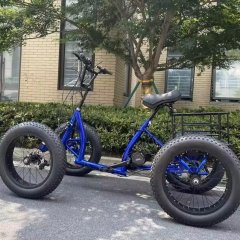
Aliexpress 'Snow' Bike - Cargo BMX 4-wheeler with BBSHD

HackD

Established
Joined
Sep 11, 2019
Messages
108
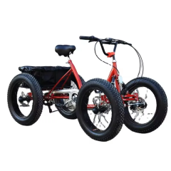
Anyone done one of these, yet? If not.. well, i guess i'm the sucker. I first saw this thing on Alibaba some months back - then on one of Sam Pilgrim's videos on youtube. I'd been looking around for a future winter project - this seems to fit the bill as the basis for one, using the basic chassis setup.

Note: i'm absolutely not fond of hammers on tubes - i'm not going to be taking Sam's mechanical gorilla approach, as in the 2nd video. He rides abusively, with the goal of finding failure for clicks and views. He seems to take the same approach, with tools. His riding skills look spot on, the rest, i reserve judgement.

Acoustic review, before ebike'd.


Electric version, with BBSHD.


The manufacturer seems to have taken *some* inspiration from this concept, or vice versa?


Mine showed up a week ago - shipping was not kind to it, with much rashed paint, several broken or bent components (rear brake assembly). Nothing critical that i wasn't going to replace out of the gate, but a bummer. The BBSHD motor showed up a few weeks before that.

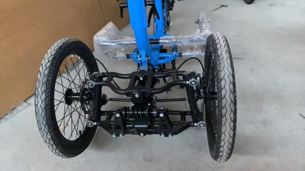
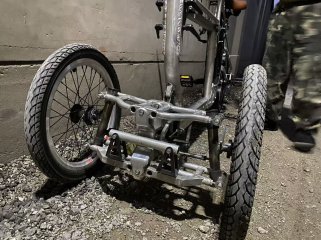
Note - i did not buy this to ride as-is, out of the box. I had somewhat lowish expectations, and this didn't disappoint. Plenty of room for improvement and opportunity for parts mix and match upgrading, much of which sits in my garage as spares. Some design aspects are 'interesting', particularly the reverse Ackerman setup.. just, why? That'll need to be fixed. A lot of it comes off as just cheap - but that's what it is, cheap, comparable to other offerings.

What this offers is tinkerability as a project basis. I do like fabricating stuff.

Goal is to make this something of a short/medium range rougher trail rider for myself, that i am beating myself (and the bike) to death on, that i am currently using a rigid Terratrike tadpole eTrike on. I am balance-challenged due to hip issues, so an eMTB is not really suitable for this sort of environment, on a personal safety basis whatever my personal ambition might foolishly say about it. My eMTB, i need to stick to the occasional curb jump.

First order is to figure out a rear differential setup, compatible to this specific rear axle. There appears to be two specific mainstream trike axles setups available (1 central affecting drive wheel on axle only, and 2 brake rotors on axle end/wheels setup) I need to determine whether the guts are essentially the same, per axle frame types, before proceeding with a commercial differential solution - then determining whether it'll be sufficiently strong enough to deal with the 160nm potential of the BBSHD. I'll do a surreptitious visit to the local well-stocked eBike shop with a micrometer and tape measure in hand - they've got a few eTrikes on display. One wheel tire-fire in the project, isn't ideal on less than smooth and hard surfaces that i am anticipating.

There's a few other major changes that will come it's way, as well - it's a basis for a project, not merely just assembly being the project itself. Still better than what i can come up with, without welding skills or equipment to build a project upon.
1753235499020.png
 
Last edited:
I can't tell what axle or diff that quad actually has, but if you want a good diff that is unliekly to fail with any power level you'd probably put thru that quad ;) , get a Peerless; they come in various sizes, and you can cut the axles it comes with and mate them to whatever live axles that has on it.

 
I can't tell what axle or diff that quad actually has, but if you want a good diff that is unliekly to fail with any power level you'd probably put thru that quad ;) , get a Peerless; they come in various sizes, and you can cut the axles it comes with and mate them to whatever live axles that has on it.
I've come to the conclusion that i'm going to address the differential issue, over the winter. It's a bit of an oddball rear end that is also on a bunch of aliexpress fat tire trikes, as well as a complete axle assembly in coaster-brake format at a dirt cheap cost. As such, the rear end might be of a quality that i might look at replacing entirely, vs upgrading. Going to give myself some time on that, given some of the shortcomings that i'm already correcting in terms of additional gussetting/bridging plates on the front end. Take it out for a few rides, before i commit to a full makeover including axle swap to something more friendly for/to a differential conversion.

The thing didn't even ship with correct length tie-rods. No wonder Sam Pilgrim's had an excess amount of toe-in. Like with mine, it would have been at the maximum point of length adjustability - about 15 mm overall too short, in order to achieve a neutral toe-in/secure purchase with sufficient threading in the tie-rods available for adjustment. On a side-note, I never did see Sam using the original seat as it came with - no wonder, it's truly hideous. Instant bin-material.

My mechanical tinker-time right now has some divided loyalties. I broke my Tadpole recumbent eTrike with a failed controller. (Golden Motors Magic Pie 5 Vector), failing after 3300km's of hard use, at 3:00am, in the middle of a freaking forest. That was fun.

I was expecting to be putting the quad-bike into service, in order to take over for some of the abusive shenanigans that i was doing with the Terror-trike, but i guess that i beat it to death, first.

Rework, and ride again.
 
Moving kind of slowly with this project.. i have come to the sudden realization that i don't think i actually have room in the garage at this moment, with a bike with this footprint.. i'm going to have to do another garage 'squeeze'.

I don't really even have room on my 'build table', in my living room..

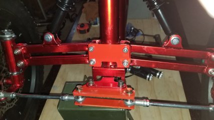
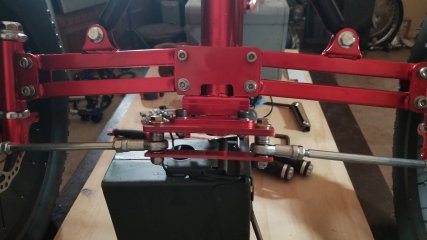
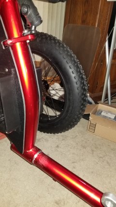
First order of business, was to assemble, and reinforce the front end. The steering tie-rods were not even/parallel to the upper/lower arms, and as mentioned in above post, too short. I made an additional 'extension bracket', with the tie-rod mounting holes about a 1/2" wider from centre, side to side. Allows for use of original tie-rods with usable adjustment, again. This also allowed me to drop the tie rods down, to get them parallel to the upper/lower arms with stiffening reinforcement with additional bottom bracket joining the two tie-rods at the bottom of the bearing surface.

In addition to this, i fabricated up a reinforcing gusset plate for the front of the upper/lower arms. Sam Pilgrim's bike broke the welds joining the brackets to the front of the frame, with the abuse that he threw at it.. i don't plan to do similar abuse, but better safe than sorry.

I've got full hydraulic brake replacements coming in for it - including a dual brake front brake setup. I'll be using 180's i've got kicking around, to upgrade the as-provided 160's for the front brakes.
 

Attachments

  • 20250817_014445.jpg
    20250817_014445.jpg
    1.3 MB · Views: 31
  • 20250817_014137.jpg
    20250817_014137.jpg
    1.1 MB · Views: 31
  • 20250817_014114.jpg
    20250817_014114.jpg
    1.1 MB · Views: 31
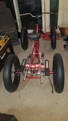
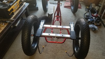
我想做点四轮的胖胎车正在调研
 

Attachments

  • 微信图片_20250902143024_52_274.jpg
    微信图片_20250902143024_52_274.jpg
    268.2 KB · Views: 26
  • 微信图片_20250902143025_53_274.jpg
    微信图片_20250902143025_53_274.jpg
    185.1 KB · Views: 26
  • 微信图片_20250902143027_54_274.jpg
    微信图片_20250902143027_54_274.jpg
    381.6 KB · Views: 26
我想做点四轮的胖胎车正在调研
Interesting photos.

I'm encountering questionable design issues with the front end of mine - i'm sure it'll be on the list of major rework items, in the future. It's a budget quad to base a project upon, after all.

Just to make mine workable to my satisfaction in the interim, i'm revising the steering methodology right off the bat. It doesn't really work as it is set up now. Not safely, anyway.

I have my work cut out for further reinforcement of the axle ends and steering tab on the front end, and i'm detecting something suspect in terms of slop and flex with it, as it is. Ideally, i need to revise the suspension arm mounts to one at least being an actual a-arm, as well as spread the arms out for more effective suspension. May involve patterning up new components to take to the welder, that can be bolted onto the existing suspension frame mounts as new sub-assemblies.

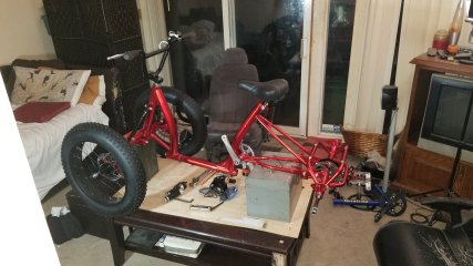
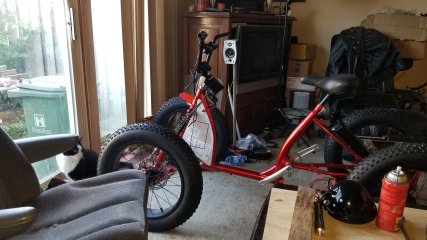
It got put on it's tires this week, in the middle of the living room. No longer sitting as a lump of components on the 'build table'.

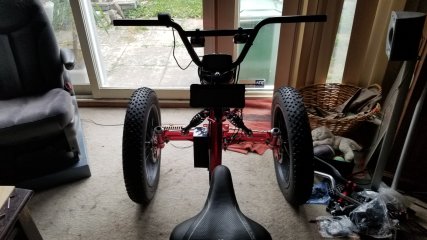
Assembled, it's bigger than i thought. I might have problems in the garage.

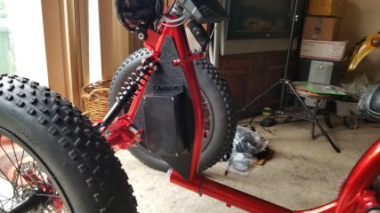
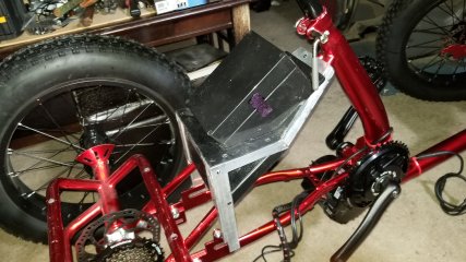
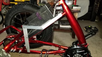
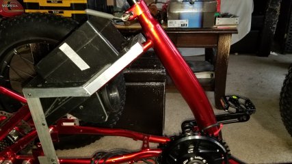
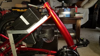
Just fooling around with mounting methodology for my twin battery packs, using components recycled from a previous project. That's on this coming weeks' to-do list.
 

Attachments

  • 20250906_004750.jpg
    20250906_004750.jpg
    1.2 MB · Views: 23
Last edited:
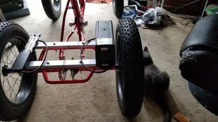
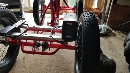
Battery subframe complete. The cat, approves.

If anyone is wondering.. no, it doesn't fit going through the patio door. It'll require the wheels coming off for that to happen, as such it'll only be a partial assembly 'in house', before i take outside to the garage to install the BBSHD and other more heavy bits and pieces.

Most of the ingredients have come in, to start working on the electrics setup for lighting, horn, etc.

1757710699770.jpeg
 
I haven't even pulled the motor out of the shipping case yet (sitting where it was deposited in front hallway 2 months ago)... but, ahaha.. visual proof, that what i thought would work with the BBSHD, will. Sam Pilgrim didn't really eyeball his motor all that well, and cut and bashed his frame to fit with in the 'correct' down position. That won't do.

The correct way to do it. WRONG - See Post #17 below for reasons. Don't do it!

1758239142642.jpeg
 
Last edited:
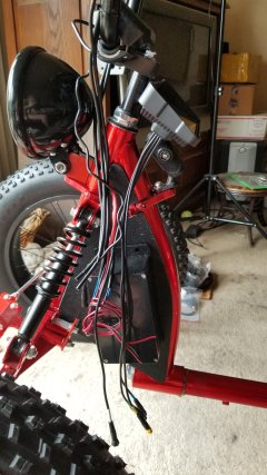
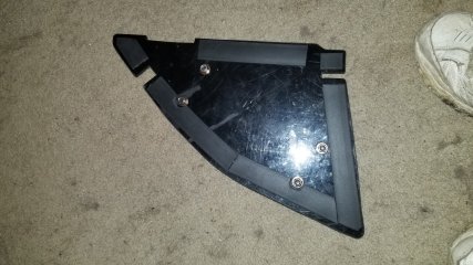
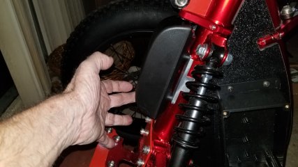
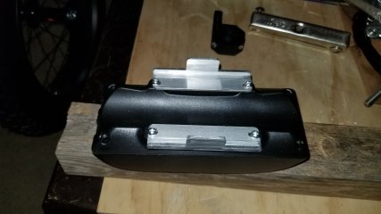
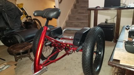
Switched gears, so to speak - working on the front end electrics setup. Part of that is paneling in the frame portion behind the steering tube, to build in a reasonably sized integral electrical junction box, where i can place the wiring connections for lighting wiring connections, horn, down-voltage converter, bus bar, and fuse box, enclosed by winged project cases on either side of the panels. This essentially makes that a hidden frame space, to feed any excessive wiring into, as well. The black sharpie rectangle, indicates the rough location footprint of those. winged project cases. They'll act as a joined compartment.

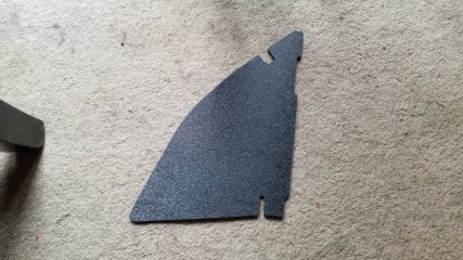
Photo shows the template that i am working with for initial material cutting. Material being used is 3/16" HDPE Board. They've already been cut out, and i'm finishing the final shaping, while i wait for the winged project cases to arrive in order to do further cutting and mounting of them to the panels on the forward bike frame.

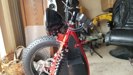
My inspiration for this, is what is done with old school Honda Passports and the like, and using frame space to hide electrical components, battery box, wiring etc out of sight and mind, behind 'side-covers'. that the winged project cases will serve as.

It'll be functional, in form and appearance. It isn't going to win any styling awards.

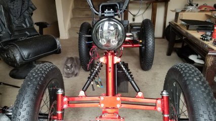
I've also fabricated and mounted a bottom mount perch onto the steering tube, for the motorcycle headlight shell. I've got a 5.75" low/high beam led headlight unit to be mounted there. Now that I see it in a photo, i have a bit of an urge to work it further with a 'speed holed' pattern on the drill press. It's a plain old chunk of aluminium without sense of style, just sort of hanging out there at present. Same goes with the battery rack, but that's a WIP.. it's all a WIP, subject to evolution/revision on the fly.
 

Attachments

  • 20250920_143345.jpg
    20250920_143345.jpg
    2.9 MB · Views: 6
Last edited:
More progress..

Two side-covers cut and finished to shape. 20250924_114712.jpg

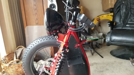
I shortened up the headlight perch, bringing the headlight bucket much closer to the steerer tube. Headlight shell assembly is a 5.75" LED unit.

20250924_114440.jpg20250924_114559.jpg

I think the logic of using concealed side-covers and adapted project cases to deal with excessive wiring, is plenty evident here. I've got lots of additional wiring to deal with, in addition to the BBSHD motor kit wiring runs Part of that is running more than a few toys.

20250924_114359.jpg

The secondary large screen that can be seen in the photo is a cheap Android auto/Apple carplay unit that i picked up to play with. It's got rear view camera features, bluetooth music streaming, as well as GPS/Mapping features through Google.. but does add to the wiring involved, as will also the additional switchgear on the handlebars/crossbar.
20250924_114440.jpg20250924_114742.jpg

With wiring out of the way, the 'project box' solution looks pretty clean. Still playing with positioning - it's secured in place at the moment with some double sided sticky tape.

20250924_114521.jpg
I brought in one of the battery packs to test fit. I might have built it out too close to the wheel. If i can get the locking key in and out, i'm good. If not, i'm going to need to cut back by about 1" (or, just slide the rim assembly off the spindle to make a bit of room to fit in the key..). The basic structure, is good however. Another wiring junction box needs to be located on the seat tube risers, for the battery cabling, and dual battery balancer module. An appropriate one is inbound, expected in a few days.

20250924_114626.jpg
 

Attachments

  • 20250924_114636.jpg
    20250924_114636.jpg
    2.8 MB · Views: 6
Last edited:
A little update, a week later. I've lined the side-panels with 1/4"x1" high density 3m rubber gasket material to make for a relatively tight seal with the bike frame. I don't think i need anything more than a couple of strategically placed jumbo zip ties, to tie the two sides onto the bike via the frame tubes themselves, very securely.

Any further work requires the electrical setup to come into play, in terms of what i am channeling into the wiring/components space, and from where, through appropriately placed wiring channels into the frame space - which requires an appropriate channeling cut, into the side-panels. Not quite there yet.

20251001_193840.jpg20251001_193949.jpg

To that end, i got a third wiring case, to locate on the steering stem, to take wiring associated with the headlight setup. Very small, but appropriate for the position. I fabricated preliminary breakout brackets to bring out the attachment points from the case, further adaptable to my needs.
20251001_194049.jpg20251001_194132.jpg

In my parts pile the past week, a component caught my eye - something i was intending to use for another project idea that died a stillborn death. Anything for an excuse to yank off a component, and give it some further work and modifications/refinement to make up something multi-function useful.

Part of a bicycle carrier for a car - i'd scavenged road-side at one point.

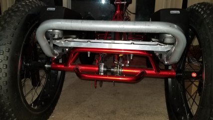
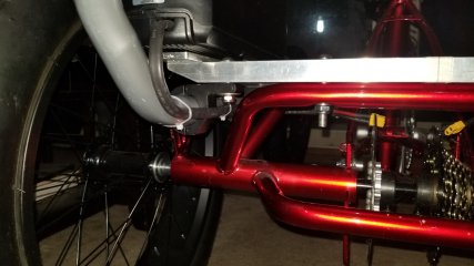
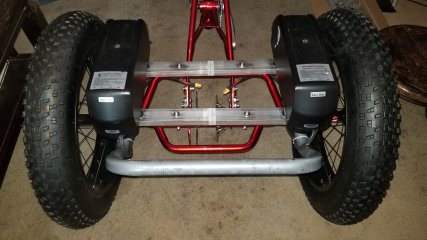
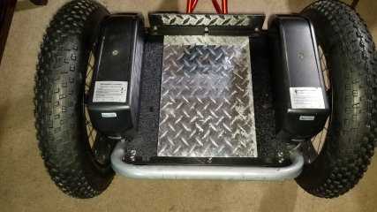
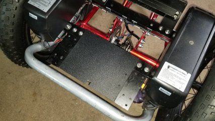
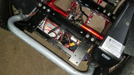
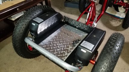
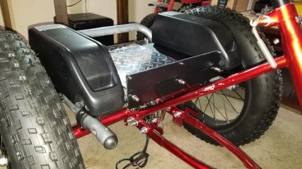
In my mind's eye, it serves the perfect role of rear bumper guard, protecting the rear of the batteries from direct impact from a roll back into a tree-trunk (for example) as well as defining the end point of a small platform, with a raised retention edge. Also a great place to do a 'safe lift' of the quad-cycle, if need be, integrated into the overall quad-cycle structure. It't secured in place with 4 roll-bar light bar 32mm clamps, dowelled in and attached to the existing frame mounted cross-beam bars for the battery mounts.

This is screaming for me to attempt a bit of carpentry with a few nice Oak slats, to make it a proper beach cruiser, in overall style.

20251001_194227.jpg20251001_193741.jpg20251001_193721.jpg20251001_193639.jpg
 
Last edited:
So... with this project, it's very much evolutional. I really have no concrete plans of how to go about to getting to my end product, except through inspiration and creative abilities. How i come to the end product, is subject to imagineering.

I had ordered another couple project boxes - but they didn't really fit the bill in terms of what i wanted in terms of durability or ideal size dimensions. My first intent was to encase the 52v-12v power inverter, the 2 battery balancer module, and all associative wiring, as well as serving as the electrical connection panels for the motor power/controller output, dual battery inputs, and charging port for the dual batteries. I believe in airflow to keep the electronics cool, so i wanted a case that acted as a 'tunnel' for volumetric active flow-through, with dual 40mm case fans acting in push-pull configuration, with part externally shielded intake / exhaust ports.

I have to do one more small electrical panel connection, for main 12v input/output. Ran out of room, on the two end panels.

20251015_161428[1].jpg20251015_161513[1].jpg

The case will then be fit to the rear of the battery rack subframe. It'll all be decked over with a removable cover, and largely weather tight with application of silicone sealant.

Measures approximately 12.5"x4.5"x4". It's been a fairly intensive 2 weeks of working on this aspect of the project, so far. I'm fairly chuffed that it actually came out nice and straight.

Time to let my progress slow a bit on this aspect of the project, pending any further inspirations, refinements, and ideas that might come to me, before i finish it to completion as a sub-assembly.

20251016_014530[1].jpg20251016_014504[1].jpg
 
Last edited:
On to paint stage for two sub-parts of the rack assembly. It's fortunate that i've got a spare bedroom 'workroom' that was pre-trashed by a previous teen larvae of the previous owner, that i can go to town in, with a window open, with the weather changing decidedly cooler the past few days.

I'll give it a few days to set before i flip, i laid on a thick yet run-free coat, miraculously. No rush, but this will allow me to part final reassemble the final combo rack assembly and start in on the wiring.


20251022_002623[1].jpg
 
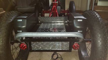
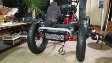
Part of the LED glow lighting now installed to rear of the bike, along with two red side marker lights shining through rear wheel spokes. This is 4 LED pods, with 6 LED's per. Integrating the lighting into the underside of the rear-deck/battery mount framing.

There are already 6 more forwards on the front end, built into the front end shrouds. Just haven't progressed to stage of wiring those in, quite yet.

I use my creations at a monthly local glow rider event, and am pre-planning/building in, accordingly, as i go along.

The overall rear deck/battery mount assembly is nearing to completion at this stage.. about 90% there, with rear tail/brake lights incoming to complete.

I'm not real happy with 'neatness' of my first wiring attempt, so will likely rip out some of what i put in today, but no biggie.. it's just apparently some more needed soldering iron practice and some more shrink tubing involved. I was attempting to retain some electrical disconnects - but i should have just clipped those out, and proceeded with all new wiring. The wiring bundle got pretty lumpy, as a result. Better to consign these LED pods to permanently mounted and wired-in use - clipping them out and replace accordingly, if they do happen to fail. Lesson learned, and about 1/2 day wasted, if i choose to redo.

 
Last edited:
FWIW, since those purple lights probably make a crapton of UV, if you want a really visible effect, you can put alternating patterns of UV-reactive paints or dyes on your rims and/or spokes, at least two inches apart. They can be clear to visible light, and only show up under UV (so they'd be visible in bright enough sunlight too).

Or just put it solid on there, even on the frame, wherever the UV from the lights will hit it, and probably double the visibility.

You can use regular dayglo paints or stickers if you want the colors to be visible all the time, but just be brighter with the UV on.


DayGlo Avenger was going to have downlights like that to light the whole frame up at night as if it was glowing from inside (it kinda already did during the day), but I never got it all done. :)
 
Almost done on the rear rack/battery bracketry assembly.
20251102_035520.jpg20251102_035634.jpg20251102_035652.jpg

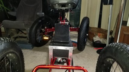
Above shows electrical component box, tied into the main battery rack frame. The PVC top slides back and free for removal, within the side channels, secured in place by two easily accessible bolts, allowing free access to everything underneath. The top is self-locking in place, in front channel.

Electrical component box is dust protected by its own separate cover. I was inspired to use the last of my 16ga checker-plate as a applique on the PVC top for both appearance, and grippage for items on the platform, that may be under a cargo net or bungee restraint.

20251102_035550.jpg20251102_035410.jpg

Found the PERFECT rear lights for this - 2" round LED units, attached to the platform top. Remove the wiring quick disconnects, and they come with the tray, as a unit. Tight integration into the overall assembly.

20251102_035426.jpg20251102_035451.jpg

A couple of more views of the overall assembly. This is built better than a Cybertruck! :LOL:

Electrical components in electrical component box is now fully wired up and functional, feeding off the dual battery balancer module. The project now lives with a fetal heart-beat. Moving onto wiring harness.
 
Last edited:
Well, Feck.

I wish i had looked at this photograph a little closer. This bike i had seen on Aliexpress, for sale around $2000.00 with the motor kit. It was clearly a single example - and no wonder. Looking at the photo, the chain stay has been bent/pounded seriously DOWN to clear the motor. It's clearly taking a quarter circle around the motor to accommodate, whereas the frame is horizontal when unmolested. Sam Pilgrim's solution while still compromising in my opinion, is the frame mod with less impact on overall frame integrity.

With the blue bike and the motor above the chain-stay, that chain-stay pounded/warped like it is - it can't be good for longevity, and my prediction is that it will likely fail catastrophically.

I'm not happy with either solution. I'll need to look at Sam Pilgrim's solution in detail, and decide how to proceed.

I had to disassemble the BBSHD into it's four major components, so that's apart now, so that i can work with the weight of just the core casting, that has the interference points on it. If i can get the frame minimally modified, and reassemble the motor around it, i might get away with that.

This was after i just dealt with a cross-threaded bearing cup in the bottom bracket, with some precise hacksaw surgery.

Just posting it here right now, in case anyone following with a similar project.

I haven't even pulled the motor out of the shipping case yet (sitting where it was deposited in front hallway 2 months ago)... but, ahaha.. visual proof, that what i thought would work with the BBSHD, will. Sam Pilgrim didn't really eyeball his motor all that well, and cut and bashed his frame to fit with in the 'correct' down position. That won't do.

The correct way to do it.

View attachment 377556
 
After a week of eyeballing it, agonizing over it, saying 'i don't wanna!!' countless times - i broke down today, committed to the 'Sam Pilgrim' fitment mod to the chainstay and end frame tube closest to the bottom bracket. It took several hours to use my great grandaddy's handed down 'no screwing around' jumbo beat-down ball-peen hammer to progressively shape the bottom of the chainstay to clear the bafang motor without splitting the tubing in the process. Success.

I didn't want to do it, but it is done. That hammer probably hasn't seen that much use, in 40 years, since grand dad passed.

Breaking down the BBSHD to it's core, made it so much lighter/easier, to fit-test, so that i could see just how close i was getting to the perfect fit. I got it close enough, without having introduced any slop, when the motor is dropped into the bottom bracket - it locks in place with no movement, as is. In retrospect, i didn't need to trim the end cap of the frame tube as much as i did.. but i trimmed less metal, than Sam Pilgrim did. A big step forwards. It wasn't as bad as i feared.

In the off chance that anyone would do this mod again with this quad and bbshd - break the motor down to the core, then beat the underside of the chainstay progressively into contoured shape to clear that portion of the motor, and then determine how much to remove the end cap and smooth the weld of the frame tube, to clear the front of the motor. I subtly re-contoured the fastener extrusion of the core case, for it to slide smoothly without friction to clear, once the frame tubing was reduced by hacksaw and contour filed first. Patience and a fine eye, is key.

Or, just buy a CYC Gen 2 instead. Apparently that goes in without any frame surgery, or beat down with a hammer.

I'll touch up the paint with hand-brushed Acrylic to protect the bare metal, and then assemble the motor in place.

20251121_232618[1].jpg20251121_232804[1].jpg
 
Last edited:
Well, after a few days.. IT'S.. IT'S ALIVE!

I must confess that i brain-farted in a major way. No damage, nothing to do with reassembly. However, it's clear that i'm getting older, and memory starts to fail. On initial reassembly, i put all the wiring connections together, put the main power into the electrical box, and was met with utter disappointment.

Bafang errored out a 04H (Throttle return error) and 30H (Controller communications failure). In addition to that, my 52v batteries with at least 2/3's charge, was showing on the display as being at 0% and the display showing red in that region of the reading. Ruh Roh. What did i do wrong? What did i Eff up? I was flummoxed for a few days. I ordered up a new BBSHD Controller a few days ago, hoping i got a defective one out of the gate, and waited.

This afternoon, while taking a nap, i had a sudden jolt awake with an out of the blue Eureka thought..

I had quick wired it up to the 12v coming out of the Voltage downconverter. I was using thick 14 ga cable for that one, as i had intentions to break that out as a main fuse box!

It had enough juice to power up the display - but everything else was non-op and displaying accordingly, obviously.

It had simply slipped my mind that i had located the 52v output, elsewhere. I then soldered up the proper main lead for the 52v connection, and wired the BBSHD up again once i had reassembled it today, and it's all good now. I can proceed forwards with the project.

I've got a spare, unnecessary 52v BBSHD controller shipping and incoming tomorrow. Rather than returning it, i might as well put it on the shelf as a spare, since i've now got 2 BBSHD equipped bikes - my original eMTB being the other one. Lessons learned - 1- double check your work *fully* from stem to stern, even the bleeding obvious you shouldn't get wrong, and 2 - give something a few days to percolate through an aging brain, before fully panicking.

 
A Further Foray into Free Form Fabrication!

(see what i did there?)

While i love the overall results with the rear battery carrier/mini-truck style platform over the rear axle, i felt that it terminated abruptly forward of the platform leaving the seat stays as wasted space on the frame, and i needed additional real estate to mount and/or hide additional modular 'Glow Rider event' options onto the bike, remove when not needed, as well as locate an intermediary wiring junction box for that purpose, built in. It'll match what i've done per the frame covers on the front sides of the bike.

Went into it with a rough idea and rough dimensions of what i wanted, and have been building it using some eyeball-aided Imagineering. It looks industrial, i'll be the first to say that about it - that seems to be my overall aesthetic with this thing, as a project. Function first. It'll be rubber mounted/separated/gapped from the battery carrier/platform as a separated assembly.

Fabricated primarily of .75" x 1/16" angle, and PVC plastic sheet of 1/4" and 1/16" thickness. This is at about the midway point of what i intend as the 'final product' Doesn't look like much with 10 days working on it, but there are quite a few hours into it now. It's hard to build up something 3-dimensional straight and true, especially when fabrication tooling is relatively rudimentary.

20251207_025255.jpg20251207_025231.jpg20251207_025203.jpg
 
. It's hard to build up something 3-dimensional straight and true, especially when fabrication tooling is relatively rudimentary.
I can't build something straight / squared up even using the right tools for the job...or draw a straight line with a ruler, so... I sympathize.

Stopped worrying much about it since the things still do the jobs I built them for. :oops:
 
I can't build something straight / squared up even using the right tools for the job...or draw a straight line with a ruler, so... I sympathize.

Stopped worrying much about it since the things still do the jobs I built them for. :oops:
I know that i'm improving, aging like a fine wine, when the patience levels have gone up, and the scrappage keeps going down in overall quantity produced. A lot of fun and imagineering to be had, when you've got the right raw materials to work with. Clearly, i now have far too much spare time on my hands right now. :LOL:

Given that 95% of it is tinker-work involving exacto knife, masking tape to direct copy desired dimensions onto material, a drill press, hand-drill, jeweller's drill, hacksaw and lots of hand-filing, i get pretty close to 'straight' overall. Within a mm or so of desired dimensional accuracy, anyway. I've also learned to compensate for minor mistakes, by fabrication method.

Most importantly, i've learned to set it aside if getting frustrated or tired, before effing things up worse. Come back to it in a timely manner with a fresh perspective and whatever redo is necessary, before you compound the error by building around any error that has been made. That does happen when you are working with little more than 'concepts of a plan', rather than any plan itself.

Overall, it's not too shabby for a guy who is/was a career social worker, moonlighting as a Gyro Gear-loose.
 
Given that 95% of it is tinker-work involving exacto knife, masking tape to direct copy desired dimensions onto material, a drill press, hand-drill, jeweller's drill, hacksaw and lots of hand-filing, i get pretty close to 'straight' overall
I usually use powertools. Much faster to do my screw ups with, and more complete destruction. :lol:

That does happen when you are working with little more than 'concepts of a plan', rather than any plan itself.
Despite me making plans for most everything (somteimes quite detailed), the results frequently don't show this. When I was much younger, my mom made me a sign a lot like this for my room door:
1765246893938.png
 
More fiddle-work. building upon the wiring input gland fastened to the bottom of the wiring box on the seat-stay platform, i've added on bracketry to mount up a 'Glow Ride' specific quick-remove disco-light module. It's not a big thing, but nice to be able to custom build/accommodate these sort of things, from the jump. Not the greatest of photos, but gives you the idea of without/with the disco light in it's mount. removable sheet side shrouding will be extended down over the rear mount points, going forward so that mount point will be entirely unnoticed, with the light module removed.

20251210_084533.jpg20251210_084512.jpg
 
So modularly designed, that it can be thrown back together as major subassemblies from bare frame in 10 minutes, for a quick fit-check. 20251210_103004[1].jpg

20251210_102945[1].jpg
 
Back
Top