• Hello ES! We could use some help to get us past the finish line on building the new knowledgebase for the forum.
    Can you donate? Please see our fundraising page. Thank you!

Aliexpress 'Snow' Bike - Cargo BMX 4-wheeler with BBSHD

The first time i laid eyes on this thread back in July, I wondered why an angle grinder and welder was not included - or at least optional. The amount of labor you've blessed this beast with so far, is impressive(y), to say the least. I just hope like hell the core frame survives - praying that single step-over tube doesn't suddenly buckle.
A major weakness in those rear axles is 15mm of unknown steel. The Schwinn meridian had/has repeated axle breakage and occasional bearing failures, ultimately losing a wheel w/axle stub still attached - a subtle warning to avoid stacking excessive weight on it. I'll check-in periodically to offer what I can to help boost your moral and build success. Now about that Z50 over there....>
 
The first time i laid eyes on this thread back in July, I wondered why an angle grinder and welder was not included - or at least optional. The amount of labor you've blessed this beast with so far, is impressive(y), to say the least. I just hope like hell the core frame survives - praying that single step-over tube doesn't suddenly buckle.
A major weakness in those rear axles is 15mm of unknown steel. The Schwinn meridian had/has repeated axle breakage and occasional bearing failures, ultimately losing a wheel w/axle stub still attached - a subtle warning to avoid stacking excessive weight on it. I'll check-in periodically to offer what I can to help boost your moral and build success. Now about that Z50 over there....>
Thanks for the compliments.. i do have an angle grinder - it sits in the bottom of the tool-box.. it's a bit overkill for this project, when at best, a Dremel would do for the 'fiddle work', if i get bored of working muscles with filing to tolerances desired :LOL:

Lack of a welder/welding skills is admittedly my weak point, and on my want list. Cost of upgrading a 70 y/o 110v residential service to a 220v electrical panel upgrade is the first hurdle. A nice selection of fasteners has always been my go-to.

I'm well aware of the weaknesses of that rear axle assembly - Sam Pilgrim (youtube guy who basically tests bikes to destruction) tested/abused one of these with lots of side-loading and stair-descending abusive treatment not conducive to keeping things together long term, and broke the driven axle clean off the bike in a slide. To mitigate this, my strategy was to put the main weight in the batteries as close in to the wheels themselves, so that the weight wasn't working the bearings with axle flexing, The ultimate goal, should the rear axle assembly survive long term/the bike doesn't get disassembled to serve as basis for new project. is to eventually replace the internals entirely at a machine shop, with a differential setup.. that's where the 'custom work' will truly begin. I also plan to pick up a replacement axle as a spare, to stick in the corner of the garage, 'just in case'. Questionable Chinesium metal alloys are always a matter of guess-work!

In a previous life, i was a motorcyclist with a few sidecars of Eastern European (Soviet era) origin. They too shared that undersized sidecar axle problem. Both sidecar axles got bent to heck and back, in sideways slides on gravel. That was fun, replacing those. Both, coincidently, were also just a mere 15mm in diameter. In that case, the axles weren't heat-treated, hardened steel.. which meant they bent, vs developing cracks and breaking under side-loading. My last sidecar (not of east European origin) got major-projected, in which i replaced the complete suspension setup, with an automotive stub axle and bearing assembly to mount a proper 4x100 auto rim assembly to it, vs the trailer based wheel and stub-axle setup, that it had previously.

I, myself weigh only around ~125 lbs soaking wet... so that was definitely a factor/compensator in overall loading considerations, and frame stressors. Keeping front end weight addition down, is definitely desirable, to keep from stressing that main tube as a potential point of failure. The front end itself is a bit sketchy in design, and is a point of failure as it was - i hope i have mitigated the stressors on that with additional plating, to keep the existing welds from separating, in lieu of having welding capabilities to reinforce it.

There has been an additional review of this setup that has appeared on Youtube, since i acquired the project - the title was apt. The bike is essentially 'rubbish', built for a low price point. Going into it, i assessed it as having some 'fun potential', with mechanical mitigation/reinforcing. I think i'm on the right track for achieving this, to my specific needs/wants.


The Z50 is part of my previous focus on Honda LSM's as a hobby. That one was a restoration that is Living Room display quality. I've also got a C70 Passport that has been awaiting an 88cc kit for, well, about a decade or so now. I've got everything needed to complete that, but my focus on ebikes the past few years has since distracted me away from it. There's a few CT70's in parts or whole, also waiting for a return in focus - including reworking a 140cc version that was a previous project.
 
Last edited:
Lack of a welder/welding skills is admittedly my weak point, and on my want list. Cost of upgrading a 70 y/o 110v residential service to a 220v electrical panel upgrade is the first hurdle.
FWIW, you can get 110v welders...even though the harbor fright $99 (over a decade ago, anyway) special I use as a backup is not the greatest, it does work and I have built and fixed numerous things successfully with it even as just a wire-feed fluxcore type.

The entrance fee to at least starting to learn to weld is pretty cheap. Looks like HF still has the same welder for not much more, only $125. https://www.harborfreight.com/flux-125-welder-57798.html

The main one I use runs on 220 (240, whatever ;) ) with a long extension I built out of some server-room power cable to my dryer outlet. I think this is the closest version to that nowadays; it's actually now on clearance for much cheaper than mine was back then (2012/13?): https://www.harborfreight.com/170-amp-dc-240v-migflux-cored-welder-57865.html

Stick welders are probably even cheaper.
 
If HF purchasing flux core only, I would probably recommend up one notch to the Titanium ($149?), because it's inverter based and weighs 15 pounds less. Could be more efficient too.

There is also Vevor littering ebay. I have one of their TIG machines and it's definitely doable (not an endorsement for TIG), and not overly disappointed. Personally I would point to a machine that, at least, has the internal guts & features for bolt-on upgrading to MIG, if you decide later on, but using it initially for flux. Be advised, flux core wire is at twice as expensive as solid core (MIG).
 
Last edited:
Front end of the quad came apart again, for a finalized 'Suspension boss reinforcement kit' to keep the front end welds from being spread out, as per Sam Pilgrim's experience. In addition to that, additional mounting points built in as brackets to hold a small rack, lighting module (see below) between the front wheels, etc., and steering linkage extension brackets cleaned up and painted.

Doesn't look like much, but not too shabby for work done with a drill press, handsaw, and filing only. Very time intensive.

20251220_043500[1].jpg
Assembled together in rough configuration of front, back and side plate brackets, to bracket-reinforce the front suspension bosses.

20251220_062738[1].jpg

On the front end.

20251220_092600[1].jpg20251220_092714[1].jpg20251220_092830[1].jpg

Where am i going, with this? As mentioned before, this Quad-bicycle will be very much involved in local 'GlowRider' events (I'm a parade marshall).. and as such am incorporating as much warning/traffic control/safety related lighting for intersection control as possible. One of thich, is a 96x16 LED Matrix panel that i picked up several years ago, but couldn't successfully integrate into existing bikes i have (far too large!).

This will eventually be hung onto the front suspension mount boss brackets above, as a modular quick-remove assembly, sitting between the front wheels, while allowing lock to lock front end steering clearance. Part of this, was building up a panel framework, to fully support the panel without strain to the panel itself. Fabricated from .75"-1/32" aluminium, and pop-riveted together.

 
Last edited:
....drill press, handsaw, and filing only. Very time intensive.
Got that right.
You definitely could use a welder. If you have a community college nearby, have a one-on-one powwow the instructor(s). Non-credit night welding classes typically encourage fabricating/welding a project of your choosing... under the watchful eye of the instructor. A totally 'green', off-the-street student is usually well on their way solo in a single 2 hour MIG class. It's a great way to get started and avoiding the bad habits and no-no's. From then on, it's usually just stick time. We only required a student supplied hood, gloves and angle grinder. I always referred to it as "the night out with the boys".
 
A few days on, of 'final wrap' fabrication.

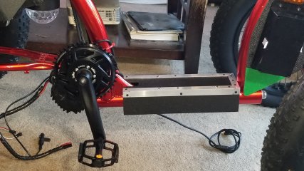
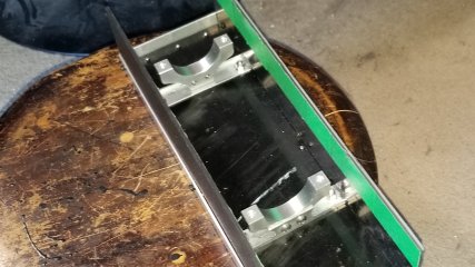
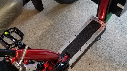
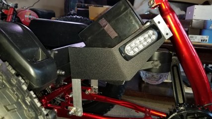
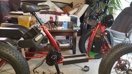
I have to protect and aesthetically hide the potentially considerable cable run/wiring loom running front to rear, so i boxed up a protective enclosure, riding upon proper 1/2" width bearing surface aluminium tubing clamps, to bridge the pivot tube and protect the cabling, and carry an led strip on the exterior.. you just gotta know that i can't resist doing that. It's got built in 'Tuck Ins' for the wiring to keep semi restrained. Nothing fancy, not particularly stylish, but neat and durable. In rough dimensional cut stage, I'm going to curve and round profile the side plastics a bit. Further detail work on that.

20260101_153144.jpg20260101_153435.jpg20260101_153552.jpg

Integration of the seat-stay electrical enclosure structure, with a full wrap to hide cable running in from rear as well as mount point for removable disco glow-ball, now pretty much finished. Running light/emergency strobe led's on either side added, because why the hell not? Mounting point tie-ins to chain-stay mount bosses, finished. Tight integration!

20260101_155116.jpg20260101_155144.jpg20260101_155201.jpg

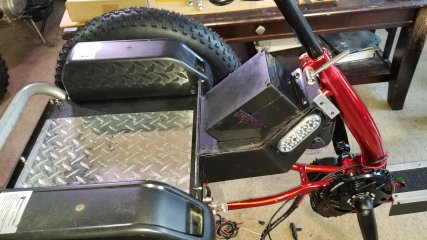
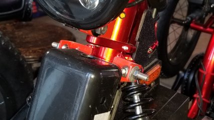
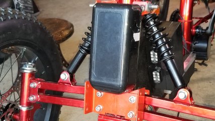
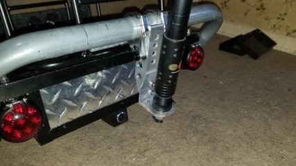
Some more small bracketry followed up the large bracketry addition to the re-worked front end pivot box-in. Upper tabs to pad onto the top shock mount points, to carry an adjustable Heim Joint rod for matrix led display suspension off main mount. Bottom large bracketry fits in very nicely with the primary wiring box in place, for the front end.

20260101_153259.jpg20260101_153329.jpg

I put my metal-working tools back into the garage - i might be pretty much done in that aspect, now.

Now focusing down to the electrical side of things, specifically the lighting harnesses/sub harnesses, figuring out how i want to segment it logically. This will include some fabrication of 3d custom cable run mounts with epoxied in plug in points for the sub harness runs. That should keep me busy for a month or two.
 
Inspiration struck this week. I had a need for a couple of 12v cigarette lighter power ports, to be placed somewhere. I also had an unused void-space created within the seat-stay downtube module, where it meets the flatbed module. I opened up the void space on the rear of the downtube module, and the flatbed module was ported through on the back-stop to allow a free-floating power port panel to be mounted, entering into the downtube module to integrate into the overall wiring harness.

20260110_085815[1].jpg

This wasn't planned, but definitely fortuitous.. the Bluetooth speaker that i use for glowride events (many bluetooth speakers in use - synchronized on a common playlist, prior to ride start) fits as snug as a bug in a rug, on the back-stop of the flatbed.

20260110_085759[1].jpg

Flush-mount USB wiring ports on the sides of the downtube module.
20260110_085832[1].jpg

10" led running lights obtained and installed on the frame tube wiring shroud.

20260110_092157[1].jpg
 
Last edited:
Two days work.

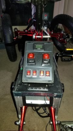
Two lower switches for 12v lighting accessories for rear bed, flanking hour meter. Two upper switches are 30a for 52v and 12v mains power. Learning some rudimentary 3d file creation skills for faceplates.

Building out the wiring infrastructure, and making connections!

20260114_230240[1].jpg20260114_230157[1].jpg
 
Last edited:
Another week's work - looks like a small thing, but isn't as it was fairly time intensive. I 3D fabricated a control box of own design (learning some 3d software skills!) and soldered together the gathered components, to centralize the control of the 2 pairs of emergency flashers/regular running lights front and back, as well as the pair of running lights, which has either steady state or chaser pattern option, on the bottom tube wiring cover.

To be hung on existing bracket immediately below the Carplay display on the central tube.

The bulk of the work in terms of time, is in the sub-assembly details and lots of patience with moderately arthritic hands.

This was a first test print, 'proof of concept' to make sure enough room for wiring components..

20260118_004103[1].jpg

Which finalized to this version.

20260122_070821[1].jpg20260122_070800[1].jpg
 
Last edited:
Wow, over a month has passed by, since last update. Time flies by when you are stuck into the minutia of a project i guess.

The past month has involved detail work. I wasn't happy with the slap-dash Mark I version of the secondary switchgear panel on the rear of the bike, and needed to add several more switch options for total of 4, for rear end electricals. Another kick at 3d Studio can produced some updated switch plates and a final configuration for the electrical box top.

The two large switches are intended to be the Masters for the Inverter 12v output to all ebike accessories, and the 52v main input going to the Bafang motor and core Bafang electrical functions, from the dual battery balancer. The meter at top is an Hours meter. I have yet to figure out a solution for a high voltage relay (ie 52v), triggered by a 12v input.
20260303_201129.jpg

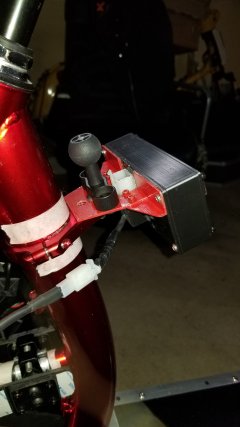
The mid-section of the bike has seen the most attention - making slow progress on this. I fabricated an aluminium bracket to tie both the carplay screen and the 3 switch emergency light control panel into the mount on the front tube clamp. The screen is off at the moment, while i work immediately below it's location. This bracket took about a weeks worth of fiddle-work, alone.

20260303_200832.jpg

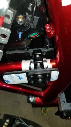
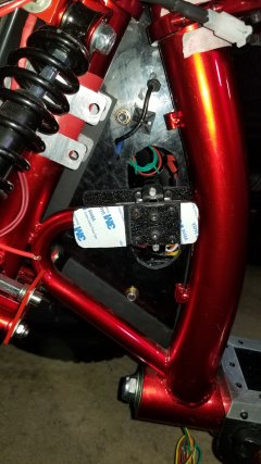
I needed to figure out a back-stop solution for the side-panels, to tie them into the frame with a removable fastener. I found the solution in a common clamp, and some fabricated spacer pads that extend out to secure the side-panels in fixed position. Doesn't look like much, but sure took some thinking and fiddling..

20260303_200810.jpg20260303_200756.jpg

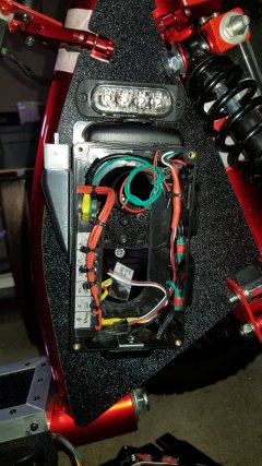
Internal wiring is well underway. This is the right hand side-panel with some of the wiring in place. What is visible, is primarily addressing the lights controlled by the emergency light switch panel. More electrics will continue to in-fill both side-panels. The frame back-stop can be seen - the interior is clearly deliberately ported, to allow additional wiring stored/run through/mounted internally as needed.

20260303_200944.jpg

Time, is starting to become a pressure point. I'd like to be able to roll this outside by middle of April. That gives me just under a month and a half away.

Lots of detail work to go, but making progress.
 
Last edited:
I finally realized a 'big ask' for my project - brake lights.

Using a separate ebike brake sensor (my hydraulic front brakes already have sensors built in for the Bafang motor disengagement - didn't want to mess with the Bafang controller in regard to that) that will be glued onto the underside of the brake lever assembly, i figured out a viable method for brake light activation. The original magnet is far too large for brake light sensor activation sensitivity - i substituted a stack of micro-sized rare earth magnets inserted into a piece of shrink tubing, that can be precisely fixed in place on the brake lever itself, for maximal activation sensitivity.

Not sure if i should be throwing a relay into the mix - i'm not really confident that the 26 gauge (?) wiring that is used with the sensor is up to the task of brake light activation, alone. That is tonight's electrical experiment.

This isn't the brake lights that i am using - just a bench test item.

Edit: well - except i smoked the sensors with 12v.. apparently they are 5v. Back to the drawing board. At least, i know the concept works in theory. It was working up to the point where i interfaced with an automotive relay wiring harness.

Apparently, i've got some more research and learning to do, about high vs low voltage and interfacing with a relay to keep a 5v circuit triggering circuit, isolated from a 12v lighting system, as it applies to function of Hall sensors, lest i let more smoke out of the wires.

I'm a relative electrics/electronics noob. I can tie together basic switches and modules with a decent wiring harness - but my knowledge is still somewhat lacking in matters beyond the basics of electric theory.

 
Last edited:
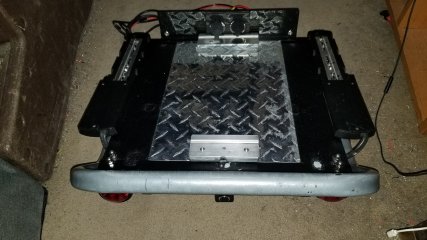
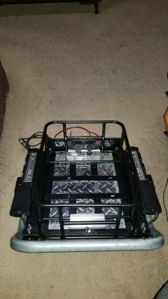
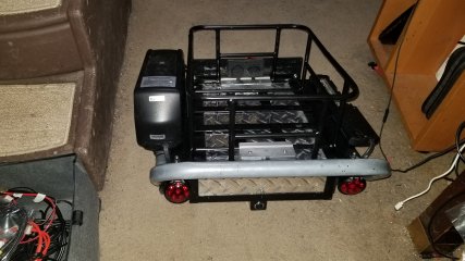
Since it appears that gas costs are going to get stupid this season, and that this is a 'Cargo quad' that is by necessity going to get some grocery-getting work in... i spotted the perfect sized basket on Amazon some time back. A compact 12x15.5" unit. I was at a loss as to how to mount it, but didn't want it to be permanently mounted. In the midst of my temporary electrical set-back, i had a moment of mechanical inspiration. An entrapment mechanism that will hold the basket firmly in place, when the top tray is slid in and bolted in place. It leaves behind the entrapment mechanism on the top tray, when the basket is not required.

20260318_053820.jpg

20260318_053658.jpg

20260318_063828.jpg
 
More progress.

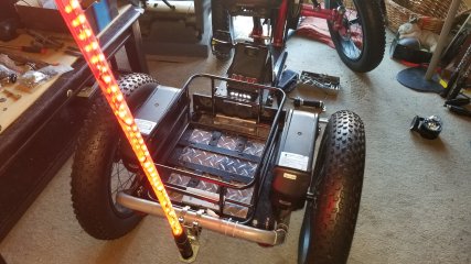
I had to fabricate an led light whip/flag pole on the project - using a pair of 30mm steering damper brackets. i built out a mount using more of my scrap aluminum stockpile. Works beautifully, but might need to redo the connection section to shorten it up, if it obscures the rear camera mount position, immediately below it. I might get away with it, depending on focal point - but i will need to have the whole rear mount assembly on the bike to hook up and check. Easy enough to redo that particular part of the mount to shorten it up, if need be.

20260324_095109.jpg


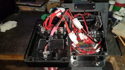
Rear section wiring is now pretty much done, with the rear wiring junction box fully filled out and wired up. A bit of an organized spaghetti mess... but it worked the first time - no smoke let out of the wiring Sir Lucas, Prince of Darkness style! This switch-controls the bed power ports, bed led illumination, led light whip, USB modules on the rear of the bike, with an inclusive fuse box.

20260324_095027.jpg

Next step is to put the rear bed and mid-mount junction assembly back on the bike, and proceed with bringing the wiring loom forwards to connect up with the side-panels.
 
Last edited:
Back bed and midsection back on - this is the final fit, before disassembly to get outside.

Now to wire up from that rear section point, going forwards. I might fabricate a wiring channel onto the left hand chain-stay to bring the wiring forwards under cover. Have to eyeball it a bit to do some Imagineering.

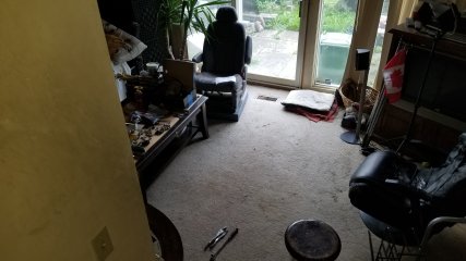
Should be easier from here on out. A LOT of wiring/fitting/rewiring/testing done the past few weeks to get that rear section 100% fully operational to my satisfaction. Time is ticking.. Shifting, brakes, chain will be left for when it's in the driveway for the reassembly, not on the rug.

20260408_162552.jpg

20260408_162534.jpg
 
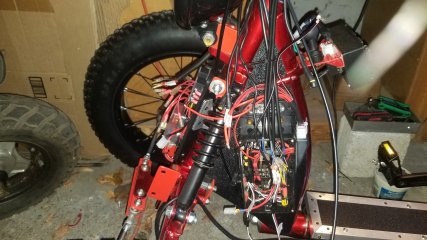
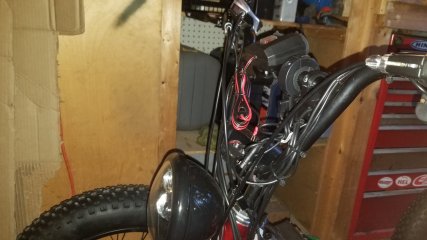
It has been a while since last update. I grossly misunderestimated time and complexity required to build up the wiring harness and accompanying electrical components from stem to stern. Lots of revisions had to be done, to further improve wiring routing/reduce wire count. 11 switchable circuits, in total.

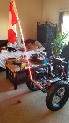
The good news, it's been disassembled and booted out of the living room, and is in process of reassembly in the driveway.

I was also distracted/slowed up by a silly as heck Trike accident mid-April, in which i somehow mounted and high-sided a parking lot curb at speed. I'm replacing the rack and subframe on that one, as a result.

The wrenches are currently flying...

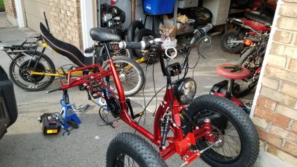
20260520_180852.jpg707739930_4538215883068762_2108120948579376547_n.jpg
 
Nearly a month on, regretfully not quite done. Health-wise, my arse is currently being kicked, with attendant lack of focus issues.

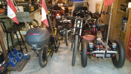
I guess progress can be noted in the state of part reassembly over the photo of May 26th, and being outside in the driveway. It managed to finally get into the garage, in terms of packing in to maximum density with big boys toy projects.

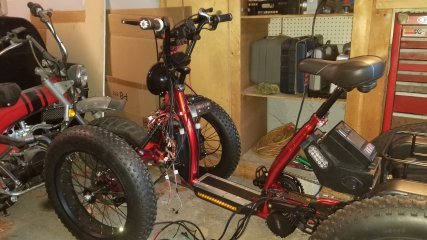
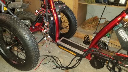
I underestimated the sheer amount of wiring involved in my electrical ambitions. It's a good thing that i built in elements that tries to at least minimize, or hide it's appearance. Every amount of space that i compartmentalized, is going to be filled with wiring once everything is finalized in terms of wiring runs. It's been a lot of soldering thus far, and almost there. Only need to provision for horn and horn mount (which can be done after final reassembly and test ride, as a plug-in, and a speed sensor mounting point on the rear.

20260620_205605.jpg20260620_205623.jpg20260620_205637.jpg20260620_205646.jpg20260620_210910.jpg
 
Back
Top