Sorry I've been away for a while.
I've had several scooters where the low speed throttle response was an issue. It's really nice when it's dialed in properly.
If the motor controller was fancy and fully programmable, this could be fixed by proper programming, but my scooters had cheap controllers with limited or no programming options.
There are a couple of factors that make this an issue.
First, look at the response of the throttle output voltage vs. throttle positon.
View attachment 349146
If you look at the curve, you'll see that it is not a straight line linear response. It's sort of "S" shaped with curved portions at the ends. The other thing to notice is the motor start voltage is quite a bit higher than the lowest throttle output. The motor start voltage has to be higher than the lowest throttle output to make sure the motor turns off when you release the throttle. Due to large variations in construction and things like temperature drift, manufacturers make a large tolerance here.
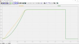
But this makes the starup happen on the steep part of the graph. If you could lower the motor start voltage, you could get it on the curved part near the end where the slope is much flatter. Since cheap controllers don't have programmable motor start voltages, the way around this is to place a resistor in series with the ground wire going to the throttle. This will shift the whole curve upward at the bottom end as shown by the green line below.
View attachment 349147
By using a multi-turn trimmer pot, you can adjust the pot so the motor barely starts running, then back off a bit. This makes a HUGE difference in the controllability at low speeds. On mine, the right resistance was around 150 ohms.
The other big factor is the controller's "operating mode", by this I mean whether it's a speed command, torque command, or something in between. Typical cheap controllers are really neither, but "PWM" command, where the throttle input controls the PWM duty cycle independent of any feedback.
With PWM command or speed command, a small, sudden increase in throttle makes the controller put out FULL power (limited only by the controller's current limit or BEMF) for a short time as the new operating point is reached.
If the controller uses a current (torque) command, a small sudden increase in throttle results in a small sudden increase in current, which is barely noticeable.
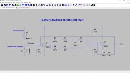
Years ago, I built a circuit that measures the battery current by using a section of the existing controller battery wire as a shunt and an op-amp that adjusts the throttle voltage to keep the battery current at level determined by the throttle setting.
View attachment 349148
This circuit took a while to get dialed in, but once adjusted, worked great. This totally eliminates the tendency to get large power surges at low speeds. The bypass switch allows you to go back to normal PWM mode and doesn't require any mods to the controller itself.
On one of my scooters, the trigger throttle was integrated into a display unit and the hall sensor was a tiny thing on a board with no easy way to mess with the wiring. On this scooter, I was able to take a small chunk of magnet and placed it in the right spot with double sticky tape to lift the low end of the curve so it behaved like the green line in the graph above. This worked great but was tricky to find the right spot for the magnet. The stock throttle magnet is to the left of the sensor in the picture:
View attachment 349149


