Another attempt at building a motor controller

No hardware over current
It was with the old ones, but with the new current sensors, that's not much of an issue anymore. I have the overcurrent detect pin routed to an interrupt pin on the Teensy, and the overcurrent detection interrupt will have higher priority than everything, including the FOC interrupt. The <~1us interrupt latency isn't going to make much of a difference when you factor in the current sensor response time + filter rise time of around 3 us. Won't save the FETs from a hard short (almost nothing will), but it will protect from pretty much everything else.

These things can kill people. Having the freedom to fettle by running 10 lines of terminal in Linux is dangerous... Any newb can change the current limits, voltage limits in a few minutes, and then face plant their onewheel or whatever when it burns.

That's a good point, but I'll mitigate it by slapping a "warranty void" sticker over the Teensy and its USB port in the final product. The code will also include a license that explicitly disclaims any warranty, along with a warning that modification / flashing of the code may cause bad things to happen, including serious injury or death.

I'll also have the WDT set up so that if the FOC interrupt fails to fire within 1.5x the expected interval, all pins will go hi-z and pullup resistors will turn all FETs off. When the chip resets from the WDT, it will refuse to even turn on a FET until power is cycled and blink an error code on the LED. This will make development somewhat safer, although I'll still be using a low-value fuse (30ish battery amps) until I'm sure it's bulletproof.

Arduino programs ("sketches") can be split up into files that handle different parts of the program. Currently, I have one for look-up tables, one for vector stuff, one for FOC and low level stuff, and one for main functions (incl. Serial communication etc).

The isolated phase sensors make synch with pwm optional... Which makes the code much more portable.
There's still a good bit of switching noise in the readout due to the current varying through the motor's inductance. I found I get better results without synchronized ADC, I have the ADC set up for max speed and have it free-run across the three phase current sense lines. I typically get around 10 ADC readings per PWM cycle per pin, and by throwing away the top and bottom quartile and average the rest. The noise in the readings drops by around 4x this way.

P.S. JLCPCB just finished producing V2, it should be here in around 5 days. Will give me some time to get ahead in my classes so I can spend a few days straight on this next weekend.
 
Now that I think about it, having a bunch of ADC readings coming in every PWM cycle would enable measuring the inductance of each phase in real-time. Inductance would simply be the slope of current vs time. I could also read it by taking the second highest minus the second lowest reading (ripple current measurement).

If I can do that, sensorless from standstill isn't that far away. Would use a good bit of CPU but that's why I went with the Teensy 4.0.
 
thorlancaster328 said:
No hardware over current
It was with the old ones, but with the new current sensors, that's not much of an issue anymore. I have the overcurrent detect pin routed to an interrupt pin on the Teensy, and the overcurrent detection interrupt will have higher priority than everything, including the FOC interrupt. The <~1us interrupt latency isn't going to make much of a difference when you factor in the current sensor response time + filter rise time of around 3 us. Won't save the FETs from a hard short (almost nothing will), but it will protect from pretty much everything else.

Read about "desat". When set up correctly, it will save the FETs from a hard short. Doesn't use current sensors at all, just monitors Vds on each fet to make sure they don't go too high. It's usually a feature that a gate driver would include, but it can be implemented with discrete components as well.
 
Good idea, but...
Everything I've read online seems to imply that desat protection is for SiC and IGBT devices only. According to the datasheet for the IRF100p218, the maximum current, even for 10 microseconds, is less than 900 amps. 1800 if you have 2 in parallel. The short circuit current of my e-bike battery is around 2.5-3 kiloamps fully charged, and others may use even more powerful batteries.

The FETs would have to deal with the short-circuit current as well as the switching energy as the FET switched off. SiC and IGBT can absorb very high transient energy spikes but I doubt that the FETs would survive. Even if they did, they would likely sustain damage from going outside their safe operating area by a large margin.

Perhaps the safest thing to do in the event of a short would be to turn all 12 FETs on at once for a few milliseconds. Then the main fuse could take the :flame: and fuses are cheaper than FETs.

Given my budget and board complexity, I can't even experiment with short-circuit protection as FETs aren't cheap. This is my main reason for not developing hard short protection. For higher-resistance shorts caused by hub motor winding insulation failure, the current sensors' FAULT outputs would be sufficient to stop the current before it got too bad. Since the hub is made of strands of thinner wire, the initial fault resistance (before the fault spread to multiple wires) would be quite high.

However, I could detect shorts at startup without too much difficulty. I could apply a minimum-width pulse to each phase at startup (a few hundred nanoseconds - just enough time for the FET to turn half on and then back off) and see if the current sensor reads anything. If it does, I would halt with an error code. I think this is what commercial controllers do as well.

I haven't heard of any commercial non-SIC/IGBT controllers with this feature.
 
I actually think you're probably good for short circuit if you get the code right. Say 80V battery and 50mohm total resistance, you've got 1600A. Your system will respond to that in 3us and it's probably just about ok. There will also be some inductance etc. If there's a motor in the circuit you're definitely ok if it's implemented right in code.

I missed that the current sensors have a fault out before, i was expecting over current on a ground referenced shunt to avoid shoot through condition... But with those FETs and gate drivers the chance of shoot through is vanishingly low as discussed before.

The most important protection I've found again and again is over voltage. If your motor regenerates, or loses synch, it's energy gets dumped back onto the power rail aggressively like an out of control buck boost converter. There's no hardware protection for that in your circuit so make very sure it's reliable in software. If your 100V FETs see a >~120V rail, they'll die instantly. If the gate driver shuts down fast, you've then got 2 mosfets in series to take that voltage so it'll survive nearer 200V spike. Caps etc might not though...
 
With my giant ~3Kwh battery, the resistance is around 40 mohm at room temperature and 30mohm if the battery heats up a bit. I'm using a battery that's larger than strictly necessary so that it runs cooler and lasts longer. With all cells charged to 4 volts, that's around 2600 amps hot and around 1900 cold shorted amps.

Still, 2 parallel FETs are rated for over half the pulse current I'm feeding them (1600 amps for 10us, even with 100v across them), so they have a good chance at surviving. I'll still put up a big warning about shorting the controller though. Definitely outside the safe operating area and it will likely degrade the FETs over time.

The most important protection I've found again and again is over voltage. If your motor regenerates, or loses synch, it's energy gets dumped back onto the power rail aggressively like an out of control buck boost converter.
Ouch. That would definitely be bad if the FETs had to eat all the power coming from the motor. With only the high-side FETs taking a phase-current avalance, they would die pretty quick.

Calculations with a 100 uh motor: Typically high performance hub motors are 50-100 uh
6 of the electrolytics I'm using, in parallel, have 6 milliohms max internal resistance. For regen currents up to 200 phase amps (max I'll support), the internal resistance would be negligible.
The max supported voltage will be 85 volts, and the FETs can take up to 110 briefly before they die (IR underspeccs their parts). That's 25 volts with 1320 uf to absorb it. Time = farads * volts/amps. That gives me 165 microseconds to respond before FETs start blowing, and around 180 microseconds until the 100v max buck converter exceeds its max ratings (I have an RC filter before the power supply)

If I just turned all the FETs off, it would take around 200 microseconds for the current in the motor to decay to zero. 100 microseconds for it to decay to half that.

That leaves me with 65 microseconds max to turn everything off once I notice the voltage rising abnormally. With ADC0 reading the battery voltage (among other things) every 8 microseconds, I can probably detect an impending overvoltage event without false positives in under 30-40 us. FET turn-off time is negligible (<1us), so I should be safe. The ADC ISR will activate the gate driver disable line directly, without waiting for the next PWM tick.

Should be safe, but I might want to add a few more bulk capacitors to the power rails just to be sure. If I added 2-3 more 220uf electrolytics on top of the 6 I already have, it should give enough safety margin to make me happy.
 
thorlancaster328 said:
With my giant ~3Kwh battery, the resistance is around 40 mohm at room temperature and 30mohm if the battery heats up a bit. I'm using a battery that's larger than strictly necessary so that it runs cooler and lasts longer. With all cells charged to 4 volts, that's around 2600 amps hot and around 1900 cold shorted amps.
Wiring, PCB etc has resistance as well! And most likely, the short has the motor partially involved.
Still, 2 parallel FETs are rated for over half the pulse current I'm feeding them (1600 amps for 10us, even with 100v across them), so they have a good chance at surviving. I'll still put up a big warning about shorting the controller though. Definitely outside the safe operating area and it will likely degrade the FETs over time.

The most important protection I've found again and again is over voltage. If your motor regenerates, or loses synch, it's energy gets dumped back onto the power rail aggressively like an out of control buck boost converter.
Ouch. That would definitely be bad if the FETs had to eat all the power coming from the motor. With only the high-side FETs taking a phase-current avalance, they would die pretty quick.

Calculations with a 100 uh motor: Typically high performance hub motors are 50-100 uh
6 of the electrolytics I'm using, in parallel, have 6 milliohms max internal resistance. For regen currents up to 200 phase amps (max I'll support), the internal resistance would be negligible.
The max supported voltage will be 85 volts, and the FETs can take up to 110 briefly before they die (IR underspeccs their parts). That's 25 volts with 1320 uf to absorb it. Time = farads * volts/amps. That gives me 165 microseconds to respond before FETs start blowing, and around 180 microseconds until the 100v max buck converter exceeds its max ratings (I have an RC filter before the power supply)
I see you have used I=Cdv/dt above and got 165us, This helps assess the time, but not the end voltage...
Consider
E=1/2LI^2 (stored inductive energy) and
E=1/2CV^2 (stored capacitor energy)
--> LI^2=C(V2^2-V1^2) --> V2=root(V1^2+LI^2/C)=root(85^2+100u*200^2/1320m)=101.26V if you dump the entire inductive energy of the motor into the rail. This happens provided you break the voltage as soon as is exceeds 85V. If you detect at 100V, it will get to 114V. 90V detect and it gets to 105V. Even a break condition will not stop this going onto the rail. If you try to recirculate it, the motor voltage will build up an even bigger current and an even bigger bang. If you break and turn off both FETs, it will still end up on the rail, but only your DCDC will suffer, since you have 2x 100V FETs. I wonder...can you protect the DCDC with a thingy. That thingy being a resistor and TVS/zener :wink: Or Set the OV to 90V and start praying TI are a bit conservative on their LM5017, and that the 200A*Rmotor gives you an extra loss factor to keep it down. Also, the battery will absorb some and clamp the voltage a bit! But with a PSU, there is no battery to absorb.

If you do not stop the PWM, then that 200A will reappear a few PWM cycles later and you end up creating potentially limitless voltages as the rotational energy of the motor is converted to electrical (like regen).

This is roughly in line with what I have measured, but First time I ran this (trivial) calc... thanks for inspiring me. Overvoltage builds up over a few PWM cycles. I previously lost synch a lot, and intentionally recreated this kind of effect. In my firmware, I now check the raw ADC reading of voltage once every PWM cycle (PWM timer triggers ADC triggers DMA triggers interrupt where I check Volts and amps before doing enything else. Latency to OV detection therefore 30us, and thus virtually impossible to kill it like that any more with my 50V battery pack. Prior to that, I wrote off piles of FETs.
If I just turned all the FETs off, it would take around 200 microseconds for the current in the motor to decay to zero. 100 microseconds for it to decay to half that.

That leaves me with 65 microseconds max to turn everything off once I notice the voltage rising abnormally. With ADC0 reading the battery voltage (among other things) every 8 microseconds, I can probably detect an impending overvoltage event without false positives in under 30-40 us. FET turn-off time is negligible (<1us), so I should be safe. The ADC ISR will activate the gate driver disable line directly, without waiting for the next PWM tick.

Should be safe, but I might want to add a few more bulk capacitors to the power rails just to be sure. If I added 2-3 more 220uf electrolytics on top of the 6 I already have, it should give enough safety margin to make me happy.
 
thorlancaster328 said:
Good idea, but...
Everything I've read online seems to imply that desat protection is for SiC and IGBT devices only. According to the datasheet for the IRF100p218, the maximum current, even for 10 microseconds, is less than 900 amps. 1800 if you have 2 in parallel. The short circuit current of my e-bike battery is around 2.5-3 kiloamps fully charged, and others may use even more powerful batteries.

....

Given my budget and board complexity, I can't even experiment with short-circuit protection as FETs aren't cheap. This is my main reason for not developing hard short protection. For higher-resistance shorts caused by hub motor winding insulation failure, the current sensors' FAULT outputs would be sufficient to stop the current before it got too bad. Since the hub is made of strands of thinner wire, the initial fault resistance (before the fault spread to multiple wires) would be quite high.
....

Your FETs aren't cheap. That's why it might be nice to have a couple dollars of parts to protect them in hardware rather than relying on firmware. Yes, if your layout is good and your FETs turn on/off when you tell them to and your firmware is working and doesn't tell them to turn on at the same time and can detect when the output is shorted before the fets blow, then you can use cheap gate drivers without desat and no stuff the desat diodes, caps, and zeners.

Until then, it probably only takes a single set of blown fets to negate the savings from not implementing desat. I'm not saying it's the only way, but you should consider it. While desat started with IGBT's, it is also useful in high power Si mosfet applications. Usually a zener diode is used to lower the desat threshold to a safe value for low Rdson devices. Tuning this circuit can take a little testing, but as long as you start with a low trip threshold and work your way up, no mosfets should be harmed. Read zombiess' posts here on the forum for examples of implementing it.
 
I wonder...can you protect the DCDC with a thingy. That thingy being a resistor and TVS/zener
That sounds like a good idea to me. If I choose a breakdown voltage of around 95 volts, it should keep the switching regulator happy during transients. Worst thing that could happen would be a zener diode failure, followed by the resistor blowing like a fuse. If I bump up the resistor to 10 ohms and install parallel zeners, I should be safe.
The version 2 boards are already on their way, but I can easily bodge the zeners in.

thepronghorn said:
Yes, if your layout is good and your FETs turn on/off when you tell them to and your firmware is working and doesn't tell them to turn on at the same time and can detect when the output is shorted before the fets blow, then you can use cheap gate drivers without desat and no stuff the desat diodes, caps, and zeners.

With the new UCC21540 gate drivers, the firmware couldn't make the FETs shoot through even if it wanted to. Deadtime is implemented in hardware. Only downside is I had to order a butt-ton of different resistor values for initial deadtime calibration.

With shoot-through impossible and loss of sync my only worry, I'll be fine as long as I do initial tests with phase fuses and no battery fuse. To push the rail over 100 volts with my 52 volt 25 milliohm ebike battery connected would require over 1800 battery amps. Simply not going to happen with my setup.
If I detect the controller losing sync, I'll do the same thing as for battery loss during regen. All FETs would switch off and the inductance would discharge into the capacitance.
In addition to faulting when the rail goes over 85, I'll also trip if the rail starts to rise rapidly at any voltage. With the 70 volt max of my current battery, it will make the setup even safer, as it will probably trip between 75-80 volts.

Usually a zener diode is used to lower the desat threshold to a safe value for low Rdson devices.
Good idea, but...
Unfortunately, I can't find any gate drivers that can drive the necessary gate current, have desat, have hardware deadtime, and are isolated.
100% hardware fault protection is a neat idea, though. In v3, I will probably rig up a NAND latch so that any short circuit detected by the current sensors sends a DISABLE signal to the gate drivers. Should be able to cut the response time from 3us down to 2.
 
IDEA:
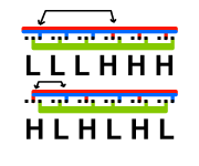
My current board layout appears to work well for a 12-FET, but with higher FET-count controllers (18 and 24), I would likely start running into issues from inductance between the bus bars (Edit: and especially the phase line)
If I have the high-side and low-side FETs grouped together (like I do currently), the current will have to flow several cm along the bus when the transistors switch. The higher inductance will increase switching losses, especially in the outer FETs.

However, if I alternate high- and low-side FETs in the power stage, the high-frequency currents will have a much shorter path to flow. Instead of several cm, the high frequency current will only have to flow from the drain of one FET to the source of another. This would reduce inductance by a factor of around 2-3, according to my unscientific estimates.

Having alternating FETs would make routing gate drive traces quite the task... but I'm already using twisted wires so this isn't a problem.

The arrow is the amount of distance the high frequency changing current would have to travel when the FETs switched.
 

Attachments

  • FetIdea.png
    FetIdea.png
    1.3 KB · Views: 807
Can't see anything wrong with this idea since you're wiring the FETs in with twisted pairs.
 
Edit: I forgot to hit submit. "Today" means February 15
New boards arrived in the mail today! I'm getting quite a bit faster with SMD soldering. I found that it works a lot faster if you apply flux, tin all the pads first, and then tack the parts on with the iron. Once I've done 1 or 2 square inches of board, a minute or so with the hot air gun results in beautiful, reliable joints.

Status so far:
Power supply: 12v and 5v working (12.6v and 5.1v = great)
Passives around Teensy for FOC measurement and stuff: Placed except for the hall sensors and CycleAnalyst shunt emulator
Gate drive: 1 of 3 placed with twisted pairs going to FETs
FETs: 4/12 soldered
Current sensors: Not placed yet
Bus bars: Not placed yet
Decoupling: Not placed yet

Only bodges I'll have to make to this board is to swap the inner two FETs in each pair to reduce inductance (See post above). Twisted pairs are fairly easy to place and allow me to make this modification with very little effort. With everything a few mm from a boatload of ceramic capacitance, there should be very little overshoot / ringing.

Haven't got any scope results yet because one of my friends borrowed it for a project. The scope should be back tomorrow morning and the boards should be done with board in a day or two. If everything works out on the hardware side it'll be time for software. Fingers crossed that saliency-based rotor detection isn't too hard.
 
Finished version 2. A lot of things look promising. Inductive turn-on is gone, current sensors are much more accurate, and the code is much simpler since I don't have to jerry-rig multiple FlexPWM timers and generate my own deadtime. However, it's not quite there yet.

First off, the gate resistors I chose are way too low. It's hard to see when the transitions end with all the ringing on the oscilloscope but it seems that the FETs are going from fully off to fully on in around 50 nanoseconds. From what I've heard / calculated, that's several times too fast. Furthermore, the ~250 ns of unnecessary dead time gives the FET's diode plenty of time to build up a nice, juicy reverse recovery charge. (I have no way of measuring the charge).

Even if I switched at a fairly slow 200 nanoseconds, each FET would only be dissipating 4.3 watts (@ 200 phase amps and 16 kHz) from switching losses. That's far less than the 18 watts they would be dissipating from conduction losses at that current. See graph at https://www.desmos.com/calculator/zcue774van

Currently I am using 2.2 ohm gate resistors, which is pretty low for a low-Miller FET like the IRF100p218. I'm going to install 4.7 or 6.8 ohm resistors but they're still in the mail and won't arrive until Thursday or Friday (I thought 2.2r might be too low).

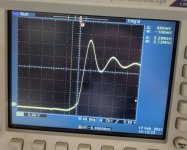
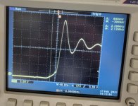
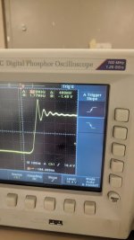
I am pleasantly surprised by how little the ringing is affected by the phase current. At 22 amps, it is only a bit worse than at 8 amps. Turn-on waveforms are cleaner than turn-off, so they aren't shown here. It appears I am switching faster than the intrinsic diode can handle.

Turn-off waveform at 8 amps
IMG_20210217_004405.jpg

Turn-off waveform at 22 amps
IMG_20210217_004416.jpg
 
Nice progress. That's the ringing with ground springs? Check also if the situation improves with scope in 10x mode. I found the scope is responsible for a large part of the ringing. Seems like a lot. Maybe that's just the price you pay for those huge to247s with their legs spread.

I'm not surprised you found the ringing to be not much worse at 22A vs 8A. I found the same. I think that contrary to the opinions of others here, the current flowing doesn't make much difference - the ringing is the resonance of the FET output capacitance and parasitic inductance and is excited by the voltage step not the current change... I ran at 4A and got no ringing, watched the scope as I grabbed the motor shell and saw no change... Posted the results... Someone declared them worthless at low current, so I re ran pushing 50A and... Got basically the same result.

What you do get is that the body diode conduction in the dead time has a significant (1-2V) impact which raises or lowers the plateau.

Decoupling will improve it as well I suspect.

I'm really pleased your inductive turn on disappeared. Allowing myself a small pat on the back for calling that one.

Keep posting. I'm learning from this! It's like... The ideas I considered but didn't do (through holes for better heat sinking, Dead time from gate drives, phase current sense...) are being tested and the results handed to me.

Switching at 16kHz you might as well be slower. I used 2R2 gate resistors and TOLL FETs for crazy fast switching because I'm targeting 35kHz+pwm to get nice sinusoids at high erpm. For mega ebike, you just don't need that.

You might find that You don't need to slow the switching all that much to make a difference - the ringing is the convolution function of the impulse response (derivative of the step response) and the input (a ramp of your switching time...) so as your switching time approaches the ringing time period it should rapidly decrease.
 
Your calculation of switching loss... I don't understand? You seen to assume that the current will ramp linearly as will the voltage...

Voltage I get, but the current? How do you figure? The current is being held constant by a massively inductive motor.

I figure your switching losses are closer to 50W for 2 FETs

16k x 200n x 100A/FET x 80V = 25.6W
 
My calculation of switching loss is based on vDS and IDS ramping linearly from the start to the end of the switching transition.

In my graph, the transition takes 200 nanoseconds and has a peak power dissipation of 2000 watts. Multiplying by 2/3 to account for the parabola being smaller than the rectangle yields a switching energy of 0.00026 joules. That times 16000 is 4.26 watts.

Redoing the calculations with a constant current load and a linearly ramping voltage, I get a peak of 8000 watts, linearly increasing / decreasing over 200 nanoseconds. That's 12.8 watts per FET. Your calculations assume that vDS and IDS are both at their max values for the entire switching transition and I don't think that's the case. Still higher than my original calculation. Now that I think about inductance your method is more correct.

I'm glad I'm using alternate-reverse SVPWM instead of standard SVPWM to drive the motor. By varying the common-mode voltage, I only have PWM one bank of FETs instead of two. This should cut switching losses in half with two FETs PWM-ing at any instant instead of 4.

Power dissipation at 200 amps phase: 18 watts * 4 (conduction losses) + 13 watts * 2 (switching losses). This assumes one phase is sourcing and one phase is sinking current. If the third phase is sharing its current with another phase the losses would be a bit less.
And 98 watts shared across 12 TO-247s on a massive 8x2x2 inch finned heatsink should be more than doable.

...
Regarding your comments on scope ringing, you're probably right. The probes I have are those ones with a 3 inch long bunny ear ground lead and a clamp on the positive end to grab a pin. When I moved the bunny ear ground wire closer to the positive, the ringing decreased a bit on the scope.

I've got ~120 uF ceramic soldered to the edge of the board. Power rails solid as a rock, no bounce there. My decoupling strategy is really paying off despite being hard to assemble.
 
Regarding manufacturability, the current board is a total nightmare. Took me over an hour to get the twisted pairs wired up and all solder joints looking clean and reliable. A twisted pair coming loose would likely blow FETs by leaving them half on.

The bus bars are also a pain to solder, especially with the current ones being dual 6 AWG wires. For the next version I will use a single pre-tinned 4 AWG wire soldered to both sides of the board. I'll also order a 150 watt iron (current one is only 50 watts max) and should be able to solder an entire bus bar at once.

Instead of twisted pairs, I'll be going for a 4-layer board for the next version. I plan on running the gate and source leads along the inner two layers of the PCB. Since the inner two layers are less than 0.5mm apart, all of the noise these traces pick up will be common-mode. By placing the decoupling capacitor between the output VDD and VSS pins, rather than between VDD and the power ground, and including a low-value (4.7r) resistor between the supply and the capacitor, I can make my gate drive immune from high-frequency common-mode noise. I'm liking these isolated gate drivers better and better.
 
mxlemming said:
Keep posting. I'm learning from this! It's like... The ideas I considered but didn't do (through holes for better heat sinking, Dead time from gate drives, phase current sense...) are being tested and the results handed to me.

Switching at 16kHz you might as well be slower. I used 2R2 gate resistors and TOLL FETs for crazy fast switching because I'm targeting 35kHz+pwm to get nice sinusoids at high erpm. For mega ebike, you just don't need that.

You might find that You don't need to slow the switching all that much to make a difference - the ringing is the convolution function of the impulse response (derivative of the step response) and the input (a ramp of your switching time...) so as your switching time approaches the ringing time period it should rapidly decrease.

Thank you for helping me out with this design. When I get the final design made (hopefully one more iteration), I can send you one. If you want I can send you one right now, I have four spare boards. The design will be open-source, so if you want to throw your brain board on it you're more than welcome to. (Although mine will probably be better because the :flame: insane :flame: performance of the IMRXT1060 in the Teensy 4.0 blows away even well-optimized code on the STM32 everyone uses)

I've only been through Calculus 1 so I have no idea what a convolution function is but your reasoning about the ringing intuituvely makes sense. Even just doubling the gate resistors might help a lot, I'll probably try that tonight by soldering 2 resistors together.
 
The design is looking promising enough that I have to decide how to release it to the public. Right now, I'm looking at three pieces of IP.
1: The board design
This will be 100% open-source. A good, easy-to-build power stage will go a long way towards helping other people with their controller projects. Not too much business value here, it's heavily based on generic Chinese controllers, just beefed up a ton.

2: The firmware in the Teensy
This will most likely be kept proprietary because this will differentiate it from all the other controllers out there. Traction control, ABS, MPPT, 120v inverter functionality, better anti-theft, etc. will be in the firmware. The firmware will use an open-source UART protocol, allowing for easy integration with other processors.
To prevent others from making knock-offs, I will spread serial number verification throughout the firmware. If the CPU has the wrong serial number, the firmware will refuse to run. The firmware will be free, though. I'll set up a webpage so people can enter their CPU serial number and download firmware if they want to flash their own.

DRM?? On an Ebike controller?? Why?? Unfortunately China has no IP protections and I could possibly see this turning into a Chinese knock-off if I provided reusable binaries. Not likely, but I still want to guard against the possibility. I might end up eventually open-sourcing this (Definitely if I stop making controllers) but once you open up your design you can't go back.

3: The firmware in the Arduino up front
This will handle the display, accelerometer data to feed the stability control, throttle and brake input, etc. This will definitely be open-source, as there is no fancy FOC code in here. This code would also be what you would tinker with to add new features (More PAS sensors, turn signals, etc). The Teensy firmware would be pretty useless to tinker with by comparison.
 
Remember... Each pwm period has a rise and a fall, hence the 2 and the half cancel out in my calc.

One day I'll accept a board. Right now I'm maxed out, just starting a new job...

Get a ground spring for your scope. You won't get meaningful results without. They're cheap... https://www.ebay.com/itm/5pcs-Multi-sized-Ground-Springs-Spare-Parts-fit-for-Tektronix-Oscilloscope-Probe/224307421026?_trkparms=ispr%3D1&hash=item3439c39f62:g:QR4AAOSw8Dxf9nUk&amdata=enc%3AAQAFAAACcBaobrjLl8XobRIiIML1V4Imu%252Fn%252BzU5L90Z278x5ickkgCVySCgrNFPU8Iu85TabMPIhtqmj3Gj18PCCHSDfLXPMv6zJ2OlvG5eECOVDIqnH525qFhyMZ5V%252B%252BJWsA48DMKxR6lPqMzj5JPYLzKAWQaw%252FkE%252FVc1BFFMYYO%252FDPcwkMXDdjri0Phj%252B9QLWoKwNro1pZygEP9c2VmKs1wxhIsY2N8PHeJgNu0UTmjbbKnbQzYQMfBlLwxMV%252FpDoXqDvJ3PeGsOMWxVQtbKiHqBQLeiF1LG6k2qCdNow5fU82wezSlTpEv3WdB9CUNXZJlrM9Yuk3pgpO4Disif7eF7L1tMAv53vrY4wx4bGt4NV%252BVLAhD3xuxUhD%252FFuv8HCM6OvgbpO1gaQYKWXhU5W45%252BLZ%252BG2yFzkFMnWuuCE5k55tci304%252Fwccf%252B2rjvnj98G%252BA1yKh6rDIYmXkfmGefmh34qWU0eVo8wB5TmQv14Y73IC3fxr5nvkJIfavG0%252BUA3aViEts7VK3vRnorCI%252BnQl22c4HtslOuQSms0bqO0bpXtzM%252FUcisOunqAkh83qTK5phcERT5K3SWzcDU%252BKCvWUKH7p2EnCkfA98GMUzGxDCC1c62tOyW%252BpO06a0I3Lox9DzXl8WwYI9zEq6JuQPjc9ERvaxVidN3mOpvIpeVmDcSQK4ZyabbBStgJk7V7R8pEvKYs00ENU%252FhCYRthq2no5gonBHf0UzLdKuTGo5Ecq%252BpYt31DjFnTgz18%252B2UzA2DFm%252Bs2dLDYVvv4APGUr%252BcyLiLt%252FT4%252BDL6Mfjx7u9bxM0ETaFw2YXZdj3YxsDCXWDvHLPLzNQ%253D%253D%7Ccksum%3A224307421026dc827609355c40aba7bbb781ba438bce%7Campid%3APL_CLK%7Cclp%3A2334524
 
Yeah, you're right. Forgot to account for the falling as well as the rising transition.

In that case, I'd have 25.6 watts/FET switching instead of 12.8, bringing the total dissipation at 200 amps and 200 ns up to 125 watts instead of 98. I'm really glad I'm only PWMing 2 FETs at a time instead of 4.

Still 99.2% efficient though :)
 
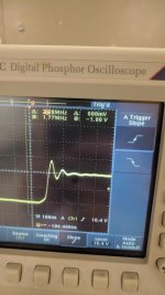
Increasing the gate resistors from 2.2r to 4.7r helped quite a bit, but the ringing is still there. Fortunately, it doesn't seem to be affected much by current and less than linearly by voltage.
At 20 amps it was nearly indistinguishable from 40 amps.
At 20 volts / 20 amps, there was 8 volts of ringing.
At 38 volts / 20 amps, there was 12 volts of ringing.
Extrapolating linearly, there would be 22 volts of ringing at 85 volts. This would be above the FETs maximum vDS for about 25nanoseconds. Even then, the FETs might not avalanche. IR is known to under-rate their parts. Even if it does avalanche, the FETs are rated at 100 amps of avalanche for 10 microseconds. A few amps for 25 nanoseconds would be nothing for the FETs.

Maybe the super low Miller charge isn't the best thing... To slow the drain-source down any more the gate-source would have to be ridiculously slow. Right now g-s takes 500 nanoseconds and d-s only 130. I'm beginning to like the IRFP4468 more and more... Only ~$4.50 apiece at Arrow

Some more scope pics (Probably the last you'll see for a while):
IMG_20210219_000352.jpg
IMG_20210218_235930.jpg

As of now, the hardware side is done. Tomorrow I start serious work on the software.

P.S. I also checked out the gate drive and it is pretty clean even at high currents. That is, unless I also attach a probe to the drain. Then the ground loop couples in noise and everything starts bouncing. I didn't try ground springs with this measurement, as it would have been a royal PITA for not much benefit.
P.P.S. Even at 30 amps for 3 minutes, the FETs were barely warm with no heatsink whatsoever. I have a good feeling about getting 200 amps out of this... if Vector ever ships my stuff.
 
Software features I plan on implementing (In no particular order):
- FOC motor control
- Sensorless Inductance-based position detection for smooth starts
- MPTA for more efficient drive of higher saliency motors
- MPPT for charging off a solar array through the hub motor's inductance
- Transformer driver so I can use an old rewound Microwave transformer to supply 1kw of 120v AC power
- Traction control (instantaneous accel, brake limiting)
- HUBWOOFER (Use your imagination)
 
If you want to try higher Miller capacitance you can always put a few pF between gate and drain with a soldering iron to simulate the other FET. I'd avoid this route since doing this puts you back into the realm of desat protection, managing oscillations on switching etc.

Doesn't really look much slower than before tbh. Bear in mind FETs have a gate resistance (typically 1.5 ohm, see the data sheet) as do gate drivers outputs (anything from 0.5 to 20 open depending on model but they're rarely clear about this... Your one says 0.5 down 5up - but it's not representative?!? in the data sheet) so the combination may not result in as much difference as you initially expect. Gate driver output is shared per fet - 4fets and it appears to have 4x the resistance from each FETs perspective.

Assuming it's not measurement error, you still have a few weapons in your arsenal - snubbers, the gate resistor at 4r7 is still pretty low.

Or try the other FETs and watch them carefully to make sure you're well away from problems.
 
I'd have a few notes.
The first bump after the rising edge is not part of the oscillation, but it is the drain current turning off and the di/dt induces voltage on the loop inductance that appears as Vds overshoot. With inductive load the rising of Vds voltage and the falling of Id current are not at the same time, but one after the other, that is called hard switching.
BTW, are you testing with inductive load (as a nearly constant current source)?
The oscillation starts just after the overshoot, because when the drain current reaches 0, there is still some overvoltage on the Coss of the FET, and that starts oscillating. You can better separate the overshoot and the oscillation at higher voltage and current, because at high current the current turn-off lasts longer (that means the overshoot is longer and higher), and at higher supply voltage the Coss is smaller, so the period of the oscillation is shorter. 8..10Vpp ringing is typical and normal here.

But a much greater oscillation is normally at the turn-on after the reverse recovery of the body diode of the non-switching FET, because the reverse recovery current of the diode falls to 0 in an instant (compared to the period of the natural frequency of the loop), and the remnant energy in the loop inductance starts the oscillation. At higher phase current the di/dt becomes higher as the FET turns on, and so the peak reverse recovery current is also higher. These oscillations are not linked to or caused by the Miller capacitance.
A typical harsh example: Irr=10A, L=20nH, Coss=1.5nF -> L*I^2 = C*U^2 -> U=36.5V, that would be the amplitude of the oscillation. This high voltage is not measured on the switching FET, but on the other one, after the rising edge of the Vds, i.e. on Coss of the non-conducting FET.
The amplitude can be reduced to an acceptable level with slower turn-on, because then the Irr is smaller, with snubbers, or by very low loop inductance as it is with SMD FETs. FETs with low reverse recovery charge are also better. If the body diode has slow reverse recovery decay, that is also an advantage, but this value is not in the datasheets, only the total reverse recovery time.
 
Back
Top