mxlemming
100 kW
- Joined
- Jul 17, 2020
- Messages
- 1,209
So I set up a quick SPICE model. First time I used spice, holy crap it is clunky. So hard to make things tidy.
I modeled the parasitic trace inductances and output capacitances you might typically see, and set the MOSFETs complimentary PWMing. I gave it 1.5nF output capacitance, 1nH top and bottom then 10nH top and bottom parasitic inductance. Gave it a battery (80V 50mohm, like a large 20s~8p kind of pack) and a bit of capacitance -1000uF with a reasonably large ESR and 100uF with a low ESR.
40uH motor coil with ~half an ohm which I varied to get the different currents.
The whole lot is chooching away at 20kHz, with 100ns dead time and 100ns rise and fall times on the "gate drivers". 10 ohm gate resistors, and it seems to model the FET gate charge... I used the biggest 100V FET I found by just scrolling down the list LTSPICE had -IPB042N10N3- it's pretty representative of the kind of FETs we use.
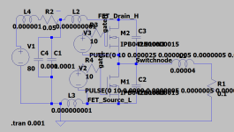
Note, this looked fairly tidy until I entered parameters and it just spewed them all over everything... Lesson for my next go - leave a LOT of space for SPICE to clutter.
1nH parasitic inductance 80A on phase node
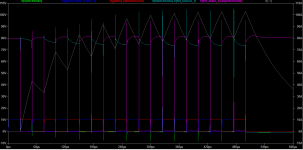
1nH parasitic inductance 80A on phase nodezoomed
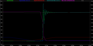
1nH parasitic inductance 160A on phase node
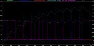
1nH parasitic inductance 160A on phase node zoomed
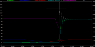
10nH parasitic inductance 80A on phase node
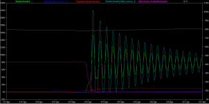
10nH parasitic inductance 80A on phase node zoomed
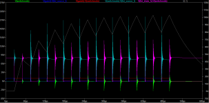
I also tried a bunch of other combinations. The slow bit is screenshoting, saving, uploading.
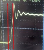
Basically, it all looks like there is a critical inductance of about 1nH and 100A, below which the ringing becomes pretty much irrelevant/manageable, frequency of the order of 25MHz, and above that it needs... managing.
It is dependent on current, but there is a lot of ringing even at low current - zero current does not imply zero ringing, so it masks the effect of current to some extent.
The importance of damping becomes clear; adding series resistance, just about anywhere, decreases the ringing time. As you would expect. Adding series resistance in the parasitic loop helps most, but... where we going to get that... that's normally exactly what we try to design out with low RDSon FETs.
Rise times that SPICE is computing are really fast, on the order of 10 ns... which is faster than the FET's rise time, so hmmm...
I am not quite sure how this stacks up with reality, and being new to SPICE, not sure whether my assumptions and inputs stand, but it does tie in pretty well with what I have observed so it can't be too far wrong...
If I input my ESC layout into https://spok.ca/index.php/resources/tools/106-traceindcalc
H=0.25, W=15, T=0.05, L=20 all mm
I get: 0.46nH
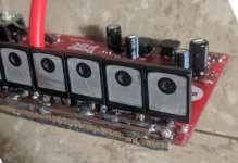
I guess this is why I get basically no ringing on my SMT TOLL fets with the ground plane right below, but Thor is getting more with his thicker 2 layer PCB with big spread wide legs on his FETs.
Summary: Make your power stages low inductance, or suffer big losses from slowing your switching right down.
I modeled the parasitic trace inductances and output capacitances you might typically see, and set the MOSFETs complimentary PWMing. I gave it 1.5nF output capacitance, 1nH top and bottom then 10nH top and bottom parasitic inductance. Gave it a battery (80V 50mohm, like a large 20s~8p kind of pack) and a bit of capacitance -1000uF with a reasonably large ESR and 100uF with a low ESR.
40uH motor coil with ~half an ohm which I varied to get the different currents.
The whole lot is chooching away at 20kHz, with 100ns dead time and 100ns rise and fall times on the "gate drivers". 10 ohm gate resistors, and it seems to model the FET gate charge... I used the biggest 100V FET I found by just scrolling down the list LTSPICE had -IPB042N10N3- it's pretty representative of the kind of FETs we use.

Note, this looked fairly tidy until I entered parameters and it just spewed them all over everything... Lesson for my next go - leave a LOT of space for SPICE to clutter.
1nH parasitic inductance 80A on phase node

1nH parasitic inductance 80A on phase nodezoomed

1nH parasitic inductance 160A on phase node

1nH parasitic inductance 160A on phase node zoomed

10nH parasitic inductance 80A on phase node

10nH parasitic inductance 80A on phase node zoomed

I also tried a bunch of other combinations. The slow bit is screenshoting, saving, uploading.
Basically, it all looks like there is a critical inductance of about 1nH and 100A, below which the ringing becomes pretty much irrelevant/manageable, frequency of the order of 25MHz, and above that it needs... managing.
It is dependent on current, but there is a lot of ringing even at low current - zero current does not imply zero ringing, so it masks the effect of current to some extent.
The importance of damping becomes clear; adding series resistance, just about anywhere, decreases the ringing time. As you would expect. Adding series resistance in the parasitic loop helps most, but... where we going to get that... that's normally exactly what we try to design out with low RDSon FETs.
Rise times that SPICE is computing are really fast, on the order of 10 ns... which is faster than the FET's rise time, so hmmm...
I am not quite sure how this stacks up with reality, and being new to SPICE, not sure whether my assumptions and inputs stand, but it does tie in pretty well with what I have observed so it can't be too far wrong...
If I input my ESC layout into https://spok.ca/index.php/resources/tools/106-traceindcalc
H=0.25, W=15, T=0.05, L=20 all mm
I get: 0.46nH
I guess this is why I get basically no ringing on my SMT TOLL fets with the ground plane right below, but Thor is getting more with his thicker 2 layer PCB with big spread wide legs on his FETs.
Summary: Make your power stages low inductance, or suffer big losses from slowing your switching right down.


