axial flux motor?

def215

10 kW
Joined
Oct 7, 2009
Messages
518
Location
philadelphia, pennsylvania
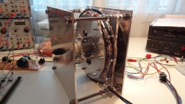
hi guys. i thought i post this in here because it is motor technology. so here the deal. i thought id experiment with axial flux motors and challenge myself to put a motor together and have it be able to work at the least. so i started playing with some scrap metal and some nuts and bolts to see what i can do. so a few weeks go by and i have this:
[youtube]LkoiBz1K9No[/youtube]
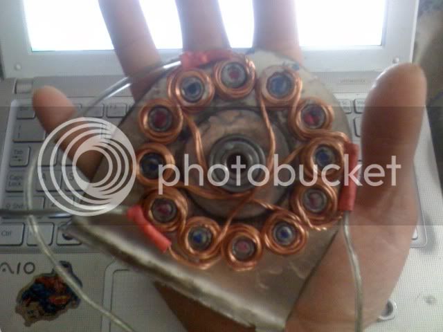
the motor is a 12tooth, 14 pole motor, wound in dlrk with 4x 22 ga. wire with 5 turrns on every tooth and terminated in delta. its 3 inches in diameter. right now im running it on my ebike controller so it has the 1/4 throttle cutout issue. but right before it cuts out at 1/4 throttle, its pulling around 5 amps or ~120watts on a 6s lipo pack at nominal voltage. i think its really low resistance motor by the way the ebike controller cuts out(my unmodified 250w 24v controller).
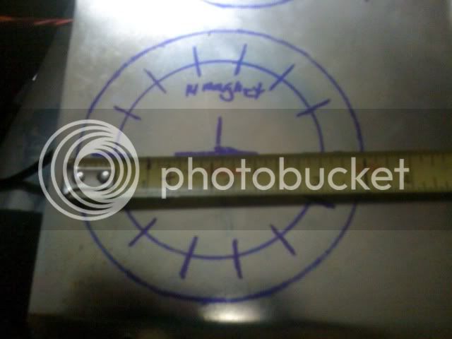
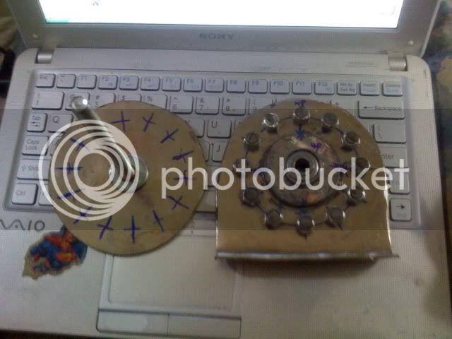
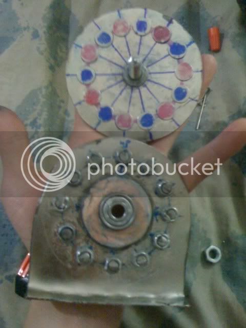
here are some pics of it when i was building it:
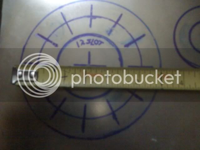
1ad0ea0e.jpg

e2ac11b7.jpg

made from sheet metal
IMG_1061.jpg

7da938d2.jpg

magnets and stator(i i guess thats what you would call it. :oops: )
IMG_1087.jpg

wound in dlrk. 4x 22 ga. with 5 turns terminated in delta.
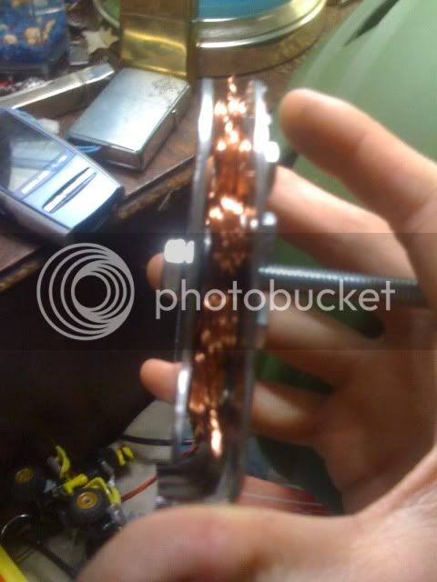
IMG_1062.jpg

the magnet gap.

i know, this was my first time building something like this and also, i had limited resources and budget. i just wanted to see if i could build something that would spin up and work and i would be happy. and also i wanted some feedback from the experts who know about this stuff. so if anyone that has constructive critism, let me have it! :lol:
 
it certainly spins so a win in my book.
Great job with such limited resources....this is more than many guys ever do so mad props def215.

you prolly already know the benifits of a laminated stator & some of the general dynamics of eddy curent generation...(wasn't so long ago i was just figuring that junk out for myself & getting a real educatoin on ellectromagnets & all the phsics involved from the brain trust around here) definatly not an expert on all the theroy...but i am gaining practical experiance pretty quickly these days.

get it working a bit smooother & you'll have the 1st submital to Miles's DIY motor challange.

way to take the lead.
 
thanks thud! props coming from a master hacker like you means a lot! :D

i did come across a reading talking about stator laminations and stuff like that because my original plan was to build a coreless axial flux, but i read that having magnetic cores made a more powerful motor. also i wasnt sure how to do laminations on a motor like this. my stator cores are completely solid and are just 10mm bolts, and i think thats why im pulling so many amps with no load. :oops: but as i did this, i learned how to wind in dlrk, which i had to do 3 times until i got right. i know i have a lot more research to do to have a fairly good working motor. :wink:

i think a sensored controller contributed a lot to this motor actually spinning because when i tested to see if it would rev all the way out on an rc controller, it just stuttered on start up and occasionally spun, very similar to ES member's enoobs inrunner alternator motor first test video that was posted a while back in his motor build thread(come to think about it, i havent seen him post in a while). his motor build thread is what inspired me to build a scratch-built motor. but im sure ill be doing a lot of tinkering to get this motor fully working and possibly making a bigger version if i get good results on this small one ive built. :roll:

ill also have more updates to this when i make progress on it also. 8)
 
thanks for the link alan!

i now can see that the motor i built technically is not an axial flux motor, but more of a pancake motor. :oops: im looking at actual axial flux motors on rcgroups and i wasnt sure how the overlapping windings really works. also it needs a halbach array to work but it can have an ironless core?

i thought you can just flatten out an rc outrunner and it will technically still work, in my case it was my 50-55 series rc motor, 12 tooth, 14-pole motor. my pancake motor shares the same amount of teeth and poles and works, but really rough. i think ill try to rewind and try to bring up the resistance because my phase wires and ebike controller im using is getting hot but the motor is just getting slightly warm. i tried measuring the resistance of the motor and i cant get any amount of measurable resistance. at least my rc motor registers a little resistance at best but it doesnt heat my ebike controller as bad as my motor i built does.
 
lebowski,

ive followed your threads of your motor build and i am really impressed with it, and beats anything ive built any day of the week. :wink: but ive noticed that your motor doesnt have an iron core in the windings. is it not necessary for that type of motor? but im guessing that is why you have magnet plates on both sides of the winding plate. and ive also noticed it was 12-tooth 14 pole. im curious to what winding pattern you used because i have mine done in DLRK.
 
def215 said:
i now can see that the motor i built technically is not an axial flux motor, but more of a pancake motor. :oops:
As I understand the terminology, axial flux simply means that the flux from magnet to coil would be parallel to the axle (magnets to teh side of the coils), and radial flux (like most of our hubmotors) would be with the magnets either radially outside or inside the coils.

So yours is indeed an axial-flux motor. Just like radial-flux types, there are variations on axial-flux as well.

This, for instance, is an axial-flux four-pole brushed motor (from a radiator fan), using a single ring magnet to the side, and AFAICT is coreless.
http://www.endless-sphere.com/forums/viewtopic.php?p=231011#p231011
file.php


file.php
 
def215 said:
lebowski,

ive followed your threads of your motor build and i am really impressed with it, and beats anything ive built any day of the week. :wink: but ive noticed that your motor doesnt have an iron core in the windings. is it not necessary for that type of motor? but im guessing that is why you have magnet plates on both sides of the winding plate. and ive also noticed it was 12-tooth 14 pole. im curious to what winding pattern you used because i have mine done in DLRK.

The way I set it up you don't need iron in the cores (and I am sure as, well, there's no argueing with a
working motor which puts out real power :D ). Iron cores is posible but would make the motor difficult
to handle. The two magnet plates in my motor attract each other (over a 8 mm airgap) with roughly
100kg of force, I need a special puller to take it apart. Can you imagine the force if I reduce the gap to 2 mm ?

The way I would go about adding iron cores if I would want this... Here in Europe they sell this garding
wire in the garden centres for tying up beanstalks and stuff. It's plastic coated 0.5 to 1 mm thick iron wire, so
it is magnetic and electrically isolated. If you wind this the same way you wind a coil but leave the endings
unconnected you have an iron core with very little eddy current losses. Just wind it while applying generous
amounts of epoxy glue (get it completely soaked) and you'll get a strong solid iron core. But you'll never be
able to take your motor apart again :mrgreen:
 
amberwolf said:
def215 said:
i now can see that the motor i built technically is not an axial flux motor, but more of a pancake motor. :oops:
As I understand the terminology, axial flux simply means that the flux from magnet to coil would be parallel to the axle (magnets to teh side of the coils), and radial flux (like most of our hubmotors) would be with the magnets either radially outside or inside the coils.

So yours is indeed an axial-flux motor. Just like radial-flux types, there are variations on axial-flux as well.

thanks for the insight amberwolf. i thought these pancake-type motors were a class of their own. i thought axial-flux motors were the ones that used the halbach array and had overlap winding. you learn something new every day. :D

Lebowski said:
The way I set it up you don't need iron in the cores (and I am sure as, well, there's no argueing with a
working motor which puts out real power :D ). Iron cores is posible but would make the motor difficult
to handle. The two magnet plates in my motor attract each other (over a 8 mm airgap) with roughly
100kg of force, I need a special puller to take it apart. Can you imagine the force if I reduce the gap to 2 mm ?

The way I would go about adding iron cores if I would want this... Here in Europe they sell this garding
wire in the garden centres for tying up beanstalks and stuff. It's plastic coated 0.5 to 1 mm thick iron wire, so
it is magnetic and electrically isolated. If you wind this the same way you wind a coil but leave the endings
unconnected you have an iron core with very little eddy current losses. Just wind it while applying generous
amounts of epoxy glue (get it completely soaked) and you'll get a strong solid iron core. But you'll never be
able to take your motor apart again :mrgreen:

generally speaking, do you think its possible to not use any iron core in the motor i have? i have a feeling that im drawing a lot of amps because of it, close to 5 amps at 1/4 throttle without load, or it might could be my low-resistance winding doing that.

when i spin it by hand, it feels very similar to my rc airplane motor, which i was going for, but im not sure if thats what i want from what im reading now. also my magnet plate that i have is made out of a ferrous metal, would i need a flux ring for the magnets before i put it on the actual magnet plate or will i be okay as long as its ferrous? i just put the magnets straight on the metal plate. :? i want to try to rewind it with thinner gauge to bring up resistance to see if it will work better. i had trouble getting the wire to fit around every tooth. a few of the winds dont sit flush to the bolts i have as magnetic cores, so i think my magnet gap is bigger than it really needs to be also. i have the halls placed at 17.14 degrees and the motor cogs hard on start up for a few seconds then starts. the motor i put together didnt turn out the way i thought it would, but i guess i know where to improve on it at now. :lol:
 
so i played with it a bit more to try to get it working correctly and i had some success and failure. after doing more google searching on dLRK winding, i believed i have done it wrong, so i rewound it with 2x26ga wire with 14turns on each tooth, instead of the 4x22ga 5turn i had on it before. and wound it the "correct" way. until i found out there were variants of dLRK winding, so i did have it "right" before. so i wound it and tested it. heres the video of that:
[youtube]NHx2f_65H9A[/youtube]
i burnt it out :evil: well i cant say that im not learning from my mistakes. :roll: now i need more magnet wire. :twisted:
 
i havent loaded it at all. :shock: 20amps is the current limit of the controller that i have things rigged up to at the moment so thats probably not good for it. but i think its due to the bolts that im using as my magnetic cores. its solid bolt heads that im using instead of something that is laminated. im guessing its suffering the effects of eddy currents because it was super hot right after that video, like i could only hold the thing in my hand for about 3 seconds when i was trying to pull it apart to inspect the windings. axial flux motors can supposedly run without magnetic cores right? i think i read that somewhere but i cant confirm that for sure. :? i know lebowski's motor doesnt use magnetic cores and right now im trying to think of a material i can use to replace my magnetic core bolts.
 
Ah...cuz that really is a LOT of power for an unloaded motor. Either there's lots of friction somewhere, or as you say: eddy currents.

The motor I posted pics of has no cores; teh windings are just flat sections cast into a plastic rotor (I don't knwo what kind of plastic, but it has not failed or deformed even after the many times I heated those things up way way past the boiling point of water...pouring water on the outside would just get me flash steam for several seconds or longer!).
 
It sounded to me like there was rubbing between the stator and rotor, creating a heck of a lot of resistance to spinning, as well as bearing chatter. I hope your next wind goes well :)

My 1/2 watt, KF
 
Nice job. I am trying to get where you guys are at. I have most of Axel Borg's books on building your own electric motors . I also have some books on homemade wind generators that I should be able to trick into thinking they are motors. Again nice job.
 
amberwolf said:
Ah...cuz that really is a LOT of power for an unloaded motor. Either there's lots of friction somewhere, or as you say: eddy currents.

The motor I posted pics of has no cores; teh windings are just flat sections cast into a plastic rotor (I don't knwo what kind of plastic, but it has not failed or deformed even after the many times I heated those things up way way past the boiling point of water...pouring water on the outside would just get me flash steam for several seconds or longer!).

i dont see anything that could be causing friction on the motor, as far as i can see. i cant feel any metal grinding when i spin it either, just the attraction of the magnets to the stator plate. now i wanna try to wind without any magnetic cores, or something thats not as big as lebowski suggested.

Kingfish said:
It sounded to me like there was rubbing between the stator and rotor, creating a heck of a lot of resistance to spinning, as well as bearing chatter. I hope your next wind goes well :)

My 1/2 watt, KF

i am running only one bearing on this motor and i cant tell if anything is rubbing when it runs but it is a possibility that there is some slop when its spinning up to speed. i gonna have to incorporate another bearing in there in the near future to take stress off of that single bearing. but i did have it screwed down to a wood floor for testing and that probably is the sound of the imperfectly cut magnet plate disc which is most likely shaking causing the sound. but taking all the things into consideration what all of you guys said, i know what to improve on now. thanks guys. :)

but i think my main issue right now is getting my winding correct, because im having a problem getting my copperfill and resistance of the winding correct so my ebike controller can run it without the 1/4 throttle cutout. :? ill get it right in time and some googling. :lol:

dynamo dave said:
Nice job. I am trying to get where you guys are at. I have most of Axel Borg's books on building your own electric motors . I also have some books on homemade wind generators that I should be able to trick into thinking they are motors. Again nice job.

thanks. i was inspired to build this motor because there was quite a few motor builds floating around here and talk about a motor building challenge so i thought id give it a shot and turn a bunch of scrap metal into something so i can have some knowledge to motorbuilding when i decide to scale up.:lol: but it took me a lot of googling, research on here and rcgroups to get to where i am now with plenty of room for improvement. :roll:

and as always, ill update when i get further with this. :mrgreen:
 
1 millon times :D
 
Back
Top