Axiom: a 100kW+ motor controller

That’s a really nice feature! I’m familiar with the concept of reluctance due to the motors Tesla uses now but I didn’t know it could be exploited to improve IPM performance.

Any chance this feature will make it to the main VESC firmware or will it be Axiom exclusive?
 
there is a 100% chance this MTPA feature will make it to VESC (@marcos) :wink:

actually, its more like 99% as we don't actually decide what gets included. we send to benjamin all of our basic stuff that is needed for the bigger power and most of the stuff needed for higher performance. but its up to him to decide what gets included and what does not.
 
Understood! Thanks for doing y’all’s part to get it into the VESC firmware. So many good contributions have come from the Axiom team. Now if we could just get the motor detection algorithm to deal with slower switching power stages better....
 
Yes! The pull request to merge MTPA is pending approval here:

https://github.com/vedderb/bldc/pull/179

We have been testing it at 800Amps on axiom and its working well. It is also under test on a smaller 150A drive with good results as well so I hope it gets merged soon.
 
Lebowski said:
With the rotation in the error signals you have the 45 degree rotation in the control loop (giving you the stability) but not in the wanted Id and Iq (so you remain FOC).

I have this 45 degree rotation in the error signals for both sensored and sensorless modes

Lebowski, are you saying the 45 deg rotation in the error signal increases phase margin? If so what happens to bandwidth, is there a trade off?
 
zombiess said:
Lebowski said:
With the rotation in the error signals you have the 45 degree rotation in the control loop (giving you the stability) but not in the wanted Id and Iq (so you remain FOC).

I have this 45 degree rotation in the error signals for both sensored and sensorless modes

Lebowski, are you saying the 45 deg rotation in the error signal increases phase margin? If so what happens to bandwidth, is there a trade off?

See explanation of the 45 degree thing here:

https://endless-sphere.com/forums/viewtopic.php?f=30&t=104895&p=1563405#p1563405
 
This was posted on hackaday, but I figured I'd share here as well

MTPA merged into VESC firmware!

MTPA stands for Maximum Torque Per Amp, which means that for a given current flowing into the motor phases it produces the maximum torque possible. We'll find out the benefits doesn't stop there.

Typical FOC implementations will drive flux-producing current (id) to zero and map the user throttle directly to the "torque generating current", (iq). This works great for cheap, non-salient SMPM motors that have a constant inductance throughout a complete revolution, but its not the complete picture.

Motors commonly found in automotive applications (Nissan Leaf, Tesla M3, BMW's, etc) are IPM motors with large reluctance that need a special algorithm to maximize the potential of the machine. Lower power IPM motors are also seen in high reliability and high dynamic range applications because the magnets aren't just glued to a surface and because they have a nice and extended constant power range.

So, will this improve my ebike or skateboard? Well, probably not much, cheap motors have usually very low saliency.

The torque equation
8891251592493930539.f562ce66152952915e4ec36107372565

From the torque equation you can draw a few conclusions:
  • iq=0 will always produce zero torque
  • id doesn't produce any torque if (Ld-Lq) is zero (an outrunner motor for example)
  • There is an optimum id,iq setpoint that maximizes the torque

The end result is something like this that shows each torque component.
8339281592491394578.f9919da6af975d8ae5c63f5d8ffa22f6


Because id,iq are 90° apart from each other, if id=0, the resulting vector angle is 0°, meaning no reluctance torque is produced. When we start adding id the reluctance torque increases, and the total produced torque becomes the sum of both traces.

By far the best thing we got out of this is understanding better the motor control theory. We developed math and reproduced equations and tools to produce a d-q axis plot of any IPM machine.

This is for example a customer's IPM motor for a custom-made extreme density motor controller we made for them.

7387911592494368523.3da17487bcf46c780d9d190da3f2a898


On a quick glance you can see at once:

  • the ideal MTPA trajectory (red)
  • how salient the machine is (how tilted the red trajectory is)
  • the current limit you are operating on (green)
  • the voltage/speed limit ellipses (blue)
  • the torque profile of the machine (orange)
  • and once you understand it you can easily see the exact id,iq currents needed to operate at any allowed speed/current target.

We also found the limitations of conventional Field Weakening algorithms and why they need to be improved if we want a linear throttle response on an IPM motor.

Side benefits!
MTPA is not only about increasing torque. The addition of id current also increases the full load base speed of the machine in the same way Field Weakening does. So you have more torque, more speed, and hence, more power!

In the Nissan Leaf motor, the improvement is huge. You can see the peak power operating point shifting from the right circle to the left towards a smaller (higher speed) ellipse while intersecting a higher torque torque curve.

589331592501387528.12f0ec7ae18bd27b5abfed0bee947806


That's right, this algorithm provides:

25% extra speed
38% extra torque
73% extra power


Implementing the optimization
You can search in the literature the details of the math to find the optimum id, iq (involves derivatives). In order to find the peak torque it boils down to this equation:

6234391592493954378.2003d218b0461c96b1aa9fde2a57709a


So the firmware will take the current reference is and separate it into the optimized id,iq components.

We added to the GUI the single parameter that controls the MTPA algorithm:

5191551592493972223.25acc32bdbb8e6d224f089363ecd375b


The Ld-Lq parameter can be measured from the vesc command line or by manually searching the peak torque on a dyno.

Besides that there were a couple of errors in both VESC firmware and in Texas Instruments app notes that had to be fixed in order for MTPA to work.

You can see the code details in the pull request to merge the new feature

https://github.com/vedderb/bldc/pull/179

Testing!
The pull request comes after long testing sessions. Let's see the algorithm in action:

3442751592493987058.e6c6a6987ffae5b9f6f2f8d5ba5e5879


In this real time plot you care about Q current (red) and D current (blue). A simpler FOC controller would keep D current at zero, but we can see how D current increases to increase the net torque in the MTPA region.

That's a light testing at 400 phase Amps, but we are regularly testing all our firmware improvements at 800A and have well exceeded the 100kW target even at lower than rated battery voltage.

A typical 800A dyno run looks like this:
5410311592494004747.59f05181f51b590b58cef8280c260d0a


And a sneak peak at a dyno run, with the motor under test on the right side:


So that's it, VESC can now make a better use of IPM motors!
 
Fantastic work!
When will you start to produce controllers for the public? If you'll sell preprogrammed controllers that will work "out of the box" on a Nissan Leaf drive train (or other specific OEM EV motors) it would make it possible for much more people to build or convert vehicles to EV :thumb:
 
The plan is to initially roll out Axiom as a Leaf-specific motor drive to provide a turn-key solution. Other motors are likely to need more support so we need to limit and optimize the amount of man-hours spent on each axiom.

We're currently working on the enclosure and planning a Rev2 board with very minor changes. Dyno testing is looking good, well over 100kW, and I expect to have field weakening fully implemented by the time we release it.
 
No sooner do I hit reply than SlowCo writes basically the exact same question... We're awash in Leaf motors right now in Houston and I got a Volvo 240 begging me to do something neat with it. Go, team, go!!!
 
WFLab - i am so jealous. its not so easy for me to get leaf motors and i need two so i can mirror Arlin's test bed and pump out tested AXIOM controllers. i like living in Canada.. but me thinks i'll have to make a trip to the USA to find leaf motors, but with COVID its been on a delay and arlin has put in the bulk of the testing work ;)
 
HighHopes said:
WFLab - i am so jealous. its not so easy for me to get leaf motors and i need two so i can mirror Arlin's test bed and pump out tested AXIOM controllers. i like living in Canada.. but me thinks i'll have to make a trip to the USA to find leaf motors, but with COVID its been on a delay and arlin has put in the bulk of the testing work ;)

Try calling some of the sellers on Ebay, many are most likely junk yards and would ship to you. Best to find one with two and make them an offer. I see plenty of them for sale.
 
zombiess said:
Try calling some of the sellers on Ebay, many are most likely junk yards and would ship to you. Best to find one with two and make them an offer. I see plenty of them for sale.

i've tried that before. $1200 CAD + 668$ shipping. its why i started all this motor controller stuff with induction motors in mind (rewound yourself) because maybe is not as power dense as a leaf motor but they are cheap and readily available everywhere in the world without shipping for dirt cheap, just visit your local motor rewind shop, there are in every city everywhere in the world.
ho hum... i'll keep searching for this elusive leaf motor (in canada)
 
@HighHopes or at @marcos

How do you guys deal with the VESC's non-ideal behavior with slower-switching hardware? I've been able to observe in my own testing that the VESC firmware depends on hardware that switches really fast in order for the motor detection and control to perform as expected. I saw that Ben had mentioned testing with phase voltage filters to possibly help with this but I haven't heard about it in a while. TI's instaspin seems to need filtered phase voltage measurements for FOC while it seems the VESC just uses the supply voltage measurement.
 
Instaspin is down right amazing. I've played quite a bit with it, but I'd need a team of smart people or a very long time to develop a controller based on it. It looks like they might have released some integration for Instaspin with Matlab Simulink since I last played with it.

I've had a tiny RC (2212 size) 1000KV motor running in FOC on 20V bus using 400A current sensors. Motor parameter detection also worked quite well. Series PI gain calculations using TI's math got me into the ball park for settings which made tuning easier. This same controller was then hooked up to a Zero motorcycles 75 series motor from a SR and worked as well after re-tuning. All of this was done with zero load on the motors making them extra difficult to control.

I'm just getting started with VESC myself, got my controller flashed last night. I'm interested to see how it works out, but most designers on here I've talked to have told me it's a bit tricky and has quirks. Guess I'll find out soon. I flashed the Axiom firmware, but I'll need to re-compile it to adjust a few pin assignments I had to make.
 
shaman said:
@HighHopes or at @marcos

How do you guys deal with the VESC's non-ideal behavior with slower-switching hardware? I've been able to observe in my own testing that the VESC firmware depends on hardware that switches really fast in order for the motor detection and control to perform as expected. I saw that Ben had mentioned testing with phase voltage filters to possibly help with this but I haven't heard about it in a while. TI's instaspin seems to need filtered phase voltage measurements for FOC while it seems the VESC just uses the supply voltage measurement.

One trick you can do is set the FOC frequency to a very low value, 5kHz for example. The lower you go the closer your measurement is to a vesc original hardware. Its still not ideal and it can be improved for sure, but it takes effort to develop a solution for that because its a hard problem, can't take that task for free right now.

VESC doesn't use phase voltages at all for R/L measurement, its probably not needed to make good parameter measurements even with slow switching hardware.
TI does something different, I think they continuously update R/L parameters while motor is running. For that you need to measure phase current AND voltage at the same time (vesc measures either phase current OR voltage). To find the motor BEMF inside the PWM output I think a lowpass filter is required. I remember TI requires 100nF at the phase voltage inputs, lebowski also uses LPF on those signals to measure BEMF.

Right now VESC can continuously measure Ld and Lq inductances while it drives the motor, still without using phase voltages. It would be cool to see a someone taking this subject as a master's thesis implemented in vesc. Using BEMF would be a big deal.
 
Axiom crew,

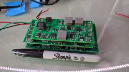
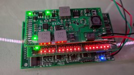
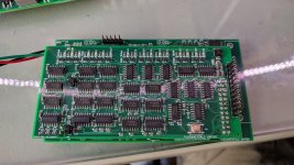
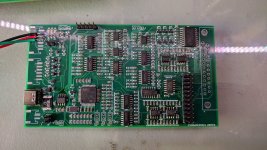
Do you know how many people have been making derivative works of your schematic? It's got some really nice features put into it. I've made some minor tweaks to it for my own use, like discrete logic in place of and FPGA for fault detection, cause I don't have time to learn how to FPGA.

This is my first version so there will be revisions, but it looks like it's going to work. Had to go to three 4 layer boards to fit into my space constraint, it also makes it modular so I can revise a board at a time.
 

Attachments

  • VESC-01.jpg
    VESC-01.jpg
    178.9 KB · Views: 3,996
  • VESC-02.jpg
    VESC-02.jpg
    195.8 KB · Views: 3,996
  • VESC-FaultLogic.jpg
    VESC-FaultLogic.jpg
    224.8 KB · Views: 3,996
  • VESC-MainBoard.jpg
    VESC-MainBoard.jpg
    248.6 KB · Views: 3,996
marcos said:
One trick you can do is set the FOC frequency to a very low value, 5kHz for example. The lower you go the closer your measurement is to a vesc original hardware. Its still not ideal and it can be improved for sure, but it takes effort to develop a solution for that because its a hard problem, can't take that task for free right now.

I've done this but then experienced issues when bumping the switching frequency back up for actual control. Detecting at 5kHz was good but then running at 20kHz was bad.

Understood that solving this would be a large task or a large check. Makes me think about the possibility though.
 
Understood that solving this would be a large task or a large check. Makes me think about the possibility though.

its a hard task but not impossible. there are MANY ways to do parameter estimation, benjamin chose one that worked for him. but there are many other ways, perhaps one of these other ways is better for slower switching modules. its an open source platform so you're free to code up your own solution too!
 
Do you know how many people have been making derivative works of your schematic?

we've never bothered to look. just keep in mind, we spend about a year coding up VESC modifications necessary to make the real high performance stuff and not all of those modifications were pushed to the open platform. so there will be some differences between AXIOM and clones. also, AXIOM uses all high end parts and i doubt that clones would do that because clones tend to focus on racing to the bottom (not saying that's what you did, just a general comment).

all the schematics we posted are for the BASIC motor controller, a high power high performance one to be sure, but its basic. textbook. there is practically nothing new in that schematic. we made it open source so everyone could afford to have a good motor controller, really get this DIY EV thing going. but there is much more to be done that IS new and unique. in the background we are working on various enhancements, things never done before, something that really cooks at power densities unheard of! so stay tuned! :)
 
Great work! It's really nice to see the continous improvements of this Project!

HighHopes said:
WFLab - i am so jealous. its not so easy for me to get leaf motors and i need two so i can mirror Arlin's test bed and pump out tested AXIOM controllers. i like living in Canada.. but me thinks i'll have to make a trip to the USA to find leaf motors, but with COVID its been on a delay and arlin has put in the bulk of the testing work ;)

I have two leaf motors sitting around. If you you need testing capacities i would love to get in touch with you. I also have enough batteries to provide a adequate power source up to 550V.
Sooner or later i need an Axiom anyway :D
 
zombiess said:
Axiom crew,

Do you know how many people have been making derivative works of your schematic? It's got some really nice features put into it. I've made some minor tweaks to it for my own use, like discrete logic in place of and FPGA for fault detection, cause I don't have time to learn how to FPGA.

This is my first version so there will be revisions, but it looks like it's going to work. Had to go to three 4 layer boards to fit into my space constraint, it also makes it modular so I can revise a board at a time.

We also have been making derivative works out of axiom for customers. It's heritage is very valuable and has been put to good use on some cool applications, some requiring a bit extreme power density figures.

Glad to see its serving you well!
 
marcos said:
VESC doesn't use phase voltages at all for R/L measurement, its probably not needed to make good parameter measurements even with slow switching hardware.
TI does something different, I think they continuously update R/L parameters while motor is running. For that you need to measure phase current AND voltage at the same time (vesc measures either phase current OR voltage). To find the motor BEMF inside the PWM output I think a lowpass filter is required. I remember TI requires 100nF at the phase voltage inputs, lebowski also uses LPF on those signals to measure BEMF.

Beginner question: What is the difference between measuring average (low-pass filtered) phase voltages, and estimating them by multiplying DC bus voltage by PWM duty cycles? Since phase currents are known, FET and shunt voltage drops can be corrected for.

When the high-side switch conducts, phase voltage should equal bus voltage. When the low-side switch conducts, phase voltage should equal ground (up to known voltage drops).
 
Out of curiosity, how does Axiom get the cold plates specified for operation? This is one of the obvious (to me) advantages of buying a pre-built Axiom, but I can think of other uses of the manufacturer's cold plates as well.
 
Out of curiosity, how does Axiom get the cold plates specified for operation?
quick answer... we know the power dissipation and where that power is dissipated. we know the capability of the cold plate to reject heat when fluid has a certain flow rate and temperature. and poof.. just like that.
 
Back
Top