
marcos
1 kW
- Joined
- Nov 19, 2016
- Messages
- 348
/***************************************************************************************/
Jump to page 11 for the latest hardware!
https://endless-sphere.com/forums/viewtopic.php?f=30&t=89056&start=250#p1458465
/***************************************************************************************/
Hi folks,
For some months I've been working on a fork of VESC thanks to resources of pymco.fr and paltatech.com The original VESC is an open source inverter for up to 50v and around 3-5kw motors, and Benjamin (vesc creator) helped me adding firmware support to this new hardware.
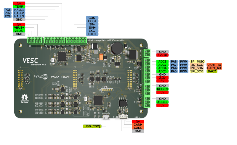
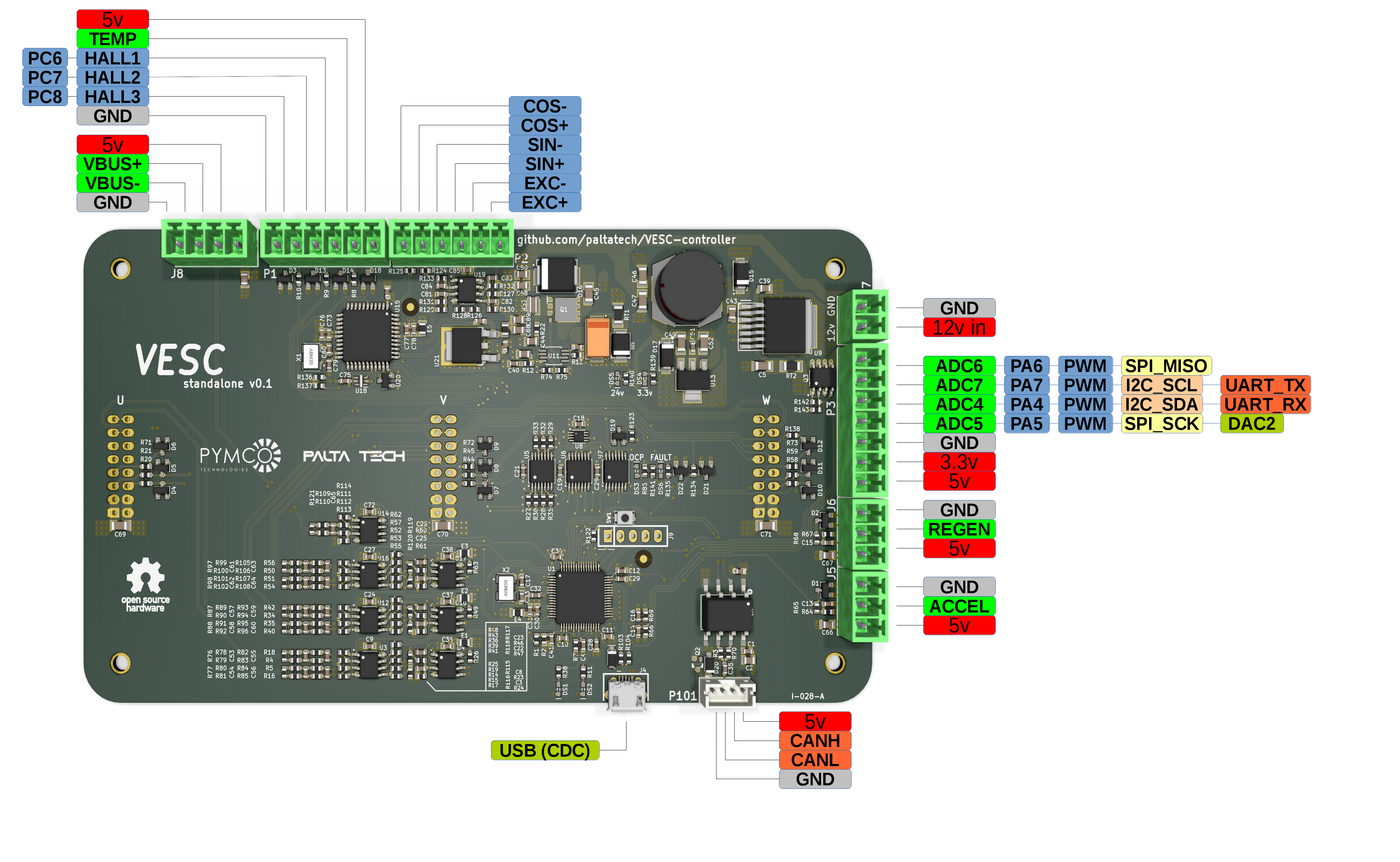
This one decouples the control logic from the gate drivers, so we can use an external gate driver for high power applications. We have a second revision working with 600V 600A IGBT modules and +/-460A current sensors, with an extensive set of hardware protections to avoid fires related to firmware bugs.
(click to enlarge)
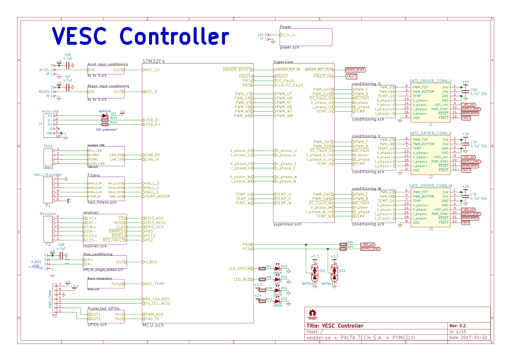
For a quick glance at the schematic, here it is
https://eyrie.io/board/6f397be723754f039735d8350260c2c0?active=schematic
And layout is here
https://eyrie.io/board/6f397be723754f039735d8350260c2c0?active=layout
Design files are in the github repo http://www.github.com/paltatech/VESC-controller
This board is made with kicad, an open source EDA. Head to http://www.kicad.org for more info about that.
Screenshot of the user interface, IMO the best GUI out there.

(click to enlarge)
And a quick video to show it spinning a motor. Its not a big motor, its not a good video either and needs some finer tuning, but that will happen on the real motor.
[youtube]7G35nryvwx8[/youtube]
A customer testing at 300V 300 phase amps
[youtube]8U7v-7AtHAY[/youtube]
These are general VESC features:
* Hardware and software is open source.
* Plenty of CPU resources left.
* STM32F4 microcontroller.
* Sensored and sensorless FOC wich auto-detection of all motor parameters
* Firmware based on ChibiOS/RT, a real time operating system.
* PCB size: 160mm x 90mm.
* Current and voltage measurement on all phases.
* Regenerative braking.
* DC motors are also supported.
* A GUI that is easy on the eyes.
* Adaptive PWM frequency to get as good ADC measurements as possible.
* Good start-up torque in the sensorless mode (and obviously in the sensored mode as well).
* The motor is used as a tachometer, which is good for odometry on modified RC cars.
* Duty-cycle control, speed control or current control.
* Seamless 4-quadrant operation.
* Interface to control the motor: PPM signal (RC servo), analog, UART, I2C, USB or CAN-bus.
* Consumed and regenerated amp-hour and watt-hour counting.
* Optional PPM signal output. Useful when e.g. controlling an RC car from a raspberry pi or an android device.
* The USB port uses the modem profile, so an Android device can be connected to the motor controller without rooting. Because of the servo output, the odometry and the extra ADC inputs (that can be used for sensors), this is perfect for modifying an RC car to be controlled from Android (or raspberry pi).
* Adjustable protection against
Low input voltage
High input voltage
High motor current
High input current
High regenerative braking current (separate limits for the motor and the input)
Rapid duty cycle changes (ramping)
High RPM (separate limits for each direction).
* When the current limits are hit, a soft back-off strategy is used while the motor keeps running. If the current becomes way too high, the motor is switched off completely.
* The RPM limit also has a soft back-off strategy.
Added features in this board:
* Hardware overcurrent protection
* Hardware pwm overlap elimination for preventing shoot-troughs
* Differential analog measurements for better noise immunity on all motor inputs (3 phase voltages, 3 currents, and dc bus voltage)
* Temperature input for each half bridge
* Isolated CAN bus for proper control
* Resolver interface (no firmware support yet)
* 9v to 30v supply voltage
* Integrated power supply for gate drivers. 15v or 24v output
This not yet a proven product, but a placeholder so if anyone wants to develop an inverter like this its possible to build upon it rather than start from scratch. I'll be making some changes in the layout and modifying bits of the design.
And if thats not enough, here is a kitten. I can get you an unicorn if you want.

Just remember the main difference between the original VESC and this: This one can kill you.
--
Marcos
Jump to page 11 for the latest hardware!
https://endless-sphere.com/forums/viewtopic.php?f=30&t=89056&start=250#p1458465
/***************************************************************************************/
Hi folks,
For some months I've been working on a fork of VESC thanks to resources of pymco.fr and paltatech.com The original VESC is an open source inverter for up to 50v and around 3-5kw motors, and Benjamin (vesc creator) helped me adding firmware support to this new hardware.
This one decouples the control logic from the gate drivers, so we can use an external gate driver for high power applications. We have a second revision working with 600V 600A IGBT modules and +/-460A current sensors, with an extensive set of hardware protections to avoid fires related to firmware bugs.
(click to enlarge)
For a quick glance at the schematic, here it is
https://eyrie.io/board/6f397be723754f039735d8350260c2c0?active=schematic
And layout is here
https://eyrie.io/board/6f397be723754f039735d8350260c2c0?active=layout
Design files are in the github repo http://www.github.com/paltatech/VESC-controller
This board is made with kicad, an open source EDA. Head to http://www.kicad.org for more info about that.
Screenshot of the user interface, IMO the best GUI out there.

(click to enlarge)
And a quick video to show it spinning a motor. Its not a big motor, its not a good video either and needs some finer tuning, but that will happen on the real motor.
[youtube]7G35nryvwx8[/youtube]
A customer testing at 300V 300 phase amps
[youtube]8U7v-7AtHAY[/youtube]
These are general VESC features:
* Hardware and software is open source.
* Plenty of CPU resources left.
* STM32F4 microcontroller.
* Sensored and sensorless FOC wich auto-detection of all motor parameters
* Firmware based on ChibiOS/RT, a real time operating system.
* PCB size: 160mm x 90mm.
* Current and voltage measurement on all phases.
* Regenerative braking.
* DC motors are also supported.
* A GUI that is easy on the eyes.
* Adaptive PWM frequency to get as good ADC measurements as possible.
* Good start-up torque in the sensorless mode (and obviously in the sensored mode as well).
* The motor is used as a tachometer, which is good for odometry on modified RC cars.
* Duty-cycle control, speed control or current control.
* Seamless 4-quadrant operation.
* Interface to control the motor: PPM signal (RC servo), analog, UART, I2C, USB or CAN-bus.
* Consumed and regenerated amp-hour and watt-hour counting.
* Optional PPM signal output. Useful when e.g. controlling an RC car from a raspberry pi or an android device.
* The USB port uses the modem profile, so an Android device can be connected to the motor controller without rooting. Because of the servo output, the odometry and the extra ADC inputs (that can be used for sensors), this is perfect for modifying an RC car to be controlled from Android (or raspberry pi).
* Adjustable protection against
Low input voltage
High input voltage
High motor current
High input current
High regenerative braking current (separate limits for the motor and the input)
Rapid duty cycle changes (ramping)
High RPM (separate limits for each direction).
* When the current limits are hit, a soft back-off strategy is used while the motor keeps running. If the current becomes way too high, the motor is switched off completely.
* The RPM limit also has a soft back-off strategy.
Added features in this board:
* Hardware overcurrent protection
* Hardware pwm overlap elimination for preventing shoot-troughs
* Differential analog measurements for better noise immunity on all motor inputs (3 phase voltages, 3 currents, and dc bus voltage)
* Temperature input for each half bridge
* Isolated CAN bus for proper control
* Resolver interface (no firmware support yet)
* 9v to 30v supply voltage
* Integrated power supply for gate drivers. 15v or 24v output
This not yet a proven product, but a placeholder so if anyone wants to develop an inverter like this its possible to build upon it rather than start from scratch. I'll be making some changes in the layout and modifying bits of the design.
And if thats not enough, here is a kitten. I can get you an unicorn if you want.
Just remember the main difference between the original VESC and this: This one can kill you.
--
Marcos
")


