marcos
1 kW
- Joined
- Nov 19, 2016
- Messages
- 348
On a side note, I've been working on improving parameter detection for this board. In order to measure the motor flux linkage the controller needs to spin up the motor, release it and then measure BEMF+rpm and with that it calculates the flux linkage.
The problem is, how does a controller spin a motor without knowing any parameter? This required the user to input 3 values for the spinning attempts (current, duty, rpm) and when I first started with this it took me days to converge to a usable tuning. It didn't spin, what should I do? Increase current? lower rpm? lower duty? Moving in a 3D space with no feedback if you are doing better was time consuming. Vesc code does 4 tries in trapezoidal mode with very different parameters (based on the parameters you input) and usually one of those random tries gets the motor to spin.
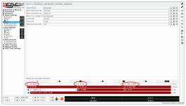
What I do now is just sending an open loop 3 phase sine to the motor that ramps up from 0 erpm to a user-defined erpm, it also ramps up the current. The whole point of making the motor spin is to make it reach a duty cycle of ~50% to make the measurement, so if your base speed is 10000erpm, you should input >5000erpm. This spinning-up process is set to take 15 seconds to ensure the motor is slowly accelerated and it doesn't go out of sync, because it is running completely openloop and some motors have large inertia. BTW there are abort mechanisms in place to detect if the motor is not spinning as it should.
Here's how it looks like. Green is the motor speed, increasing until it reaches my commanded 40% duty cycle. Orange is the voltage at one of the motor phases. Yellow is the motor position as measured by the FOC observer.
View attachment 4
The detection results are always very consistent.
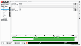
I need to double check if 22mWb is a sound value for this motor based on the kV and pole number, but I can tell after the parameter detection the motor works much better than my manual tuning.
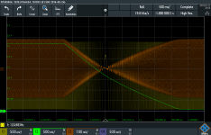
After the parameter detection you can do a sensorless full speed reversal
View attachment 1
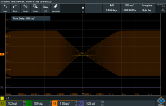
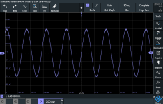
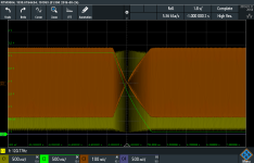
Same color coding as the first screenshot, zooming in the yellow (phase angle) being reversed. Speed and phase angle are calculated in the FOC loop and sent to 12bit dac's.
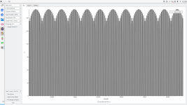
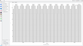
In the GUI it looks like this
This works for me at <25Amps. Higher than that it gets confused at 0 rpm, I think higher currents should help the observer keep track of motor position, but too fast position changes+no BEMF can make the output be distorted by the PI filters. I need a proper testbench to test that.
In any case, a high power motor should have a position sensor anyways so I'm not spending more time in zero-rpm sensorless operation. At least not with this no-saliency observer.
Another quick change I made was in the phase resistance measurement so it always measure with a fixed amount of Amps, it used to perform some dynamic sorcery that with this hardware wasn't consistent. I still need to compensate for the IGBT's Vce that is not a problem when you use mosfets, but its <0.5% error when you use this at the rated 400V.
Firmware changes were sent to benjamin for merging into the codebase, he's busy putting together other parts of the project but these features will be merged someday.
The problem is, how does a controller spin a motor without knowing any parameter? This required the user to input 3 values for the spinning attempts (current, duty, rpm) and when I first started with this it took me days to converge to a usable tuning. It didn't spin, what should I do? Increase current? lower rpm? lower duty? Moving in a 3D space with no feedback if you are doing better was time consuming. Vesc code does 4 tries in trapezoidal mode with very different parameters (based on the parameters you input) and usually one of those random tries gets the motor to spin.

What I do now is just sending an open loop 3 phase sine to the motor that ramps up from 0 erpm to a user-defined erpm, it also ramps up the current. The whole point of making the motor spin is to make it reach a duty cycle of ~50% to make the measurement, so if your base speed is 10000erpm, you should input >5000erpm. This spinning-up process is set to take 15 seconds to ensure the motor is slowly accelerated and it doesn't go out of sync, because it is running completely openloop and some motors have large inertia. BTW there are abort mechanisms in place to detect if the motor is not spinning as it should.
Here's how it looks like. Green is the motor speed, increasing until it reaches my commanded 40% duty cycle. Orange is the voltage at one of the motor phases. Yellow is the motor position as measured by the FOC observer.
View attachment 4
The detection results are always very consistent.

I need to double check if 22mWb is a sound value for this motor based on the kV and pole number, but I can tell after the parameter detection the motor works much better than my manual tuning.
After the parameter detection you can do a sensorless full speed reversal


View attachment 1
Same color coding as the first screenshot, zooming in the yellow (phase angle) being reversed. Speed and phase angle are calculated in the FOC loop and sent to 12bit dac's.
In the GUI it looks like this
This works for me at <25Amps. Higher than that it gets confused at 0 rpm, I think higher currents should help the observer keep track of motor position, but too fast position changes+no BEMF can make the output be distorted by the PI filters. I need a proper testbench to test that.
In any case, a high power motor should have a position sensor anyways so I'm not spending more time in zero-rpm sensorless operation. At least not with this no-saliency observer.
Another quick change I made was in the phase resistance measurement so it always measure with a fixed amount of Amps, it used to perform some dynamic sorcery that with this hardware wasn't consistent. I still need to compensate for the IGBT's Vce that is not a problem when you use mosfets, but its <0.5% error when you use this at the rated 400V.
Firmware changes were sent to benjamin for merging into the codebase, he's busy putting together other parts of the project but these features will be merged someday.


