Here is some test results we had a while ago when doing double pulse tests to validate the powerstage and our custom DC Link.
First of all, I coded some handy functions and commands to perform a double pulse test from the VESC Tool GUI.
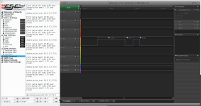
From the command line I can easily and accurately set the timing. This is a firmware patch that will be kept at our lab as tool, we won't distribute this binary but we can receive any powerstage and do this testing for you in our bench.
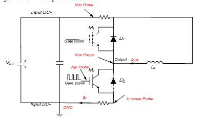
A test setup is something like this:
You want to observe the switching characteristics of the drive at peak current load. To do that you keep the top IGBT in OFF state (Our powerstage will keep the top gate at -9Vdc)
* Turn ON the bottom switch and let the current through the inductor increase to the desired test current
* Turn OFF the switch and observe the voltage overshoot
* Wait a minimum amount of time and turn ON the switch (rated current is still flowing through the body diode od the TOP switch)
We have some handy support math to calculate the construction of the inductor, the required inductance and time required to reach a set current.
A test setup looks something like this:
View attachment 3
Note that voltages are measured with differential probes to avoid damaging the oscilloscope, and measurement happens directly at the IGBT terminals
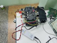
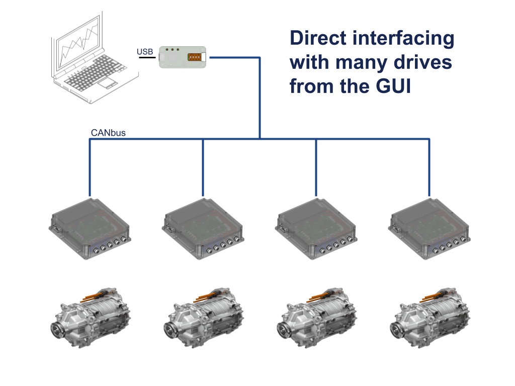
On the top left you can see the inductor for the test. We communicate to Axiom through the isolated CANbus interface so the laptop is isolated from the device under test.
Double pulse test result at 375V 450A:
View attachment 1
And zoomed in:
Yellow trace is Collector voltage (to measure overshoot), green trace is phase current, orange trace is TOP IGBT gate (to observe miller effect).
The overshoot is caused by the inductance of the path between the silicon switch and the DC Link capacitor. This includes the internal IGBT module wiring, the connection to the DC Link and the internal DC Link ESL. We tested other DC Link and ours performed better during this testing. Overshoot can change wildly if your DC Link is not carefully designed; we have a 100V overshoot, imagine how bad can it become if the DC Link ESL is left unchecked.
Overshoot must stay below the IGBT rated voltage, which is 650Vdc minus some buffer %. If we were operating at higher DC bus voltages we can either test snubbers, slow down the turn OFF time or just use a 1200V rated IGBT.
Miller capacitance between gate and collector of the TOP switch will try to turn ON that switch when its supposed to be off. We check that the gate sits at -9Vdc and miller can only pull it up to -7Vdc, thats good.
Something really good about double pulse test is that you can measure the switching losses, and we have access to a very good rogowski current probe but its only capable of measuring 300A and we are more interested into the 500A to 800A range. We did measure emitter current but the sensor can't properly track the slewrate. Maybe next time.
Double pulse testing is something
*every* controller design should have endured, you don't know how the powerstage works until you observe it.


