Bafang M560 / Tektro HD-E350 compatability

fatorangecat

1 µW
Joined
Mar 17, 2025
Messages
4
Location
Austin, TX
Hello all,

I have a bike that I recently installed an M560 on. This past weekend, I installed Tektro HD-E350 hydraulic brakes with the 2-pin red Julet connection. I ordered yellow 3-pin Julet cutoff sensors (https://a.co/d/gXFYyTm) to swap with the 2 pin, but they do not cut power when activated. I also tried swapping the nfox brake levers with 3-pin connections that I have installed and working on another bike (BBSHD UART) to test signal, but no response. I then tried shorting the pins out directly to test if I could get a response. The only response I could get was for the motor to completely shut off (display and all) when shorting out 2 of the 3 pins, requiring me to power back on. I'm assuming this is liable to damage the controller, shorting out the 5v signal, and I'm at a loss for where to continue.

Are there specific brake sensors I should be using for this CAN protocol motor? What is the motor looking to see as far as signal? Can anyone point me in the right direction? I'm trying to figure out if I should be using what I already have or if I should be buying something different.

Thanks in advance. Long time lurker, first time poster. Let me know if you'd like some photos.
 
The only response I could get was for the motor to completely shut off (display and all) when shorting out 2 of the 3 pins, requiring me to power back on. I'm assuming this is liable to damage the controller, shorting out the 5v signal, and I'm at a loss for where to continue.
Most cutoff switches only require a signal wire and ground, or 2 conductors. 3 wire cables add a 5V source for use with certain types of switches (e.g. hall based) or to use a thumb throttle for variable regen. It's likely that only the signal and ground wire are being utilized for normal brake cutoffs. The signal wire, when measuring the controller connector may show a voltage of just under 5v. That it because the controller will have a pull up resistor, pulling up the voltage of the signal wire to something like 4.8V, which when grounded via the cutoff switch, signals the controller to cut power. Note that if you accidentally grounded the 5V conductor rather than the signal wire, you could easily damage the 5V supply in the controller.
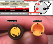
Check this post to see the pinout of the 3 pin connector. I believe this is more or less standard for the Bafang 3 pin harness.


You could carefully retest attempting to cutoff power by shorting the signal wire to ground after taking careful voltage measurements to determine which conductor is the signal wire and which is 5V first. And check that the corresponding pins on the lever also short when the lever is activated. If not, you may need to correct the wiring.
 
You could carefully retest attempting to cutoff power by shorting the signal wire to ground after taking careful voltage measurements to determine which conductor is the signal wire and which is 5V first. And check that the corresponding pins on the lever also short when the lever is activated. If not, you may need to correct the wiring.

Gotcha. So basically, I need to pull my multimeter out tonight and spend some time probing around to see what voltage readouts I'm finding, then go from there to see which connections should be getting made. I'm going to dig into it some more when I get off work. I've viewed the post you're referencing with the wiring/plug schematics, along with several others similar, but that was in a late night search for answers and my brain was fried already.

This is my first time building a frame/motor specific build (rather than BBS conversion). I found a trashed FLX F5 with all of the electricals ripped out on FB Marketplace (FLX Trail Review - for reference, same model) for $50, so I decided to try my hand with it. My first test rides with it this past weekend were exciting. That said, I'm feeling quite intimidated dealing with CANBUS vs UART, and it's leaving me with lots of questions concerning speed/throttle/brake sensor interfacing and programming. Hoping to find a good open-source alternative to BESST that without a steep learning curve.

I was very confused when none of the other 3-pin yellow brake cutoff switches I have laying around from my prior BBSHD builds (mech and hydro levers) had any action on this M560. I've plugged in mech switches and played with other hydro switches using a magnet, but no effect from any.

Additionally, this motor kit (ordered from Sing Yiu on AliExpress) did not come with brake sensors included, nor have I seen any included on photos from listings elsewhere. This leaves me curious whether brake sensors may be programed out entirely on the firmware side of things. Which leads to another can of worms I'm not keen on opening right now (programming canbus).

One more thing I should note: I didn't include brake lighting in my tests last night. There is a connection for brake lighting on the rear cable (speed/shift/rear light), and in hindsight, I should have had one plugged in while testing to see if it was lighting up.

Any additional insights you or anyone else might have on these motors would be greatly appreciated. I'll report back what I find after messing with it tonight.
 
I went and snapped some quick photos of what I'm working with for reference:


The bike
PXL_20250317_175544617.MP.jpg

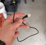
Mechanical sensor switch
PXL_20250317_180029976.MP.jpg

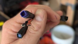
Rear interface cable (left: speed/shift/lighting, right: motor input)
PXL_20250317_175939633.jpg

2-pin (red) and 3-pin (yellow) hydro brake switches
PXL_20250317_175825012.jpg

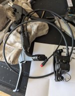
Tektro HD-E350 front brake assembly (unmodified/uninstalled, stock 2-pin switch). spare mechanical brake with switch removed seen in background.
PXL_20250317_175705440.jpg

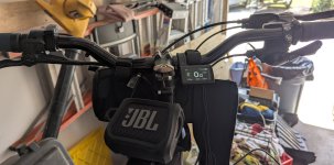
showing handlebar/display/throttle setup. rear brake from Tektro HD-E350 pair installed with sensor removed for 2-pin/3-pin swap.
PXL_20250317_180105385.jpg
 
Last edited:
Also, stripped mechanical sensor switch I was using for probing last night. Accidentally broke the 3-pin connector a moment ago, so I snipped it off to peek which pins the wire colors correspond to. I may strip the other identical switch tonight for additional probing purposes. (My probes are too large to fit in the female connector's sockets, so I'd rather work with a stripped male plugged in.)
PXL_20250317_175728380.jpg
 
FWIW, many (not all) of the 3 pin switches use a hall sensor like those in a motor or speed sensor. These are "open collector" so that just like the two wire switches, the signal itself is a 5v signal from the controller that is grounded by the hall turning on as the magnet is pushed close to it by the switch plunger. The only functional difference is the hall requires 5v power where the switch doesn't.

In the previously linked thread, this image shows which pins are which on most of these connectors, to help you connect and test the right wire to ground for turning on the brakes.
1742243406504.png


There are also some 3 pin brake levers/switches that use *analog* hall sensors (like throttles do), to implement variable regen braking for DD hubmotors and clutchless/freewheelless chain/belt drives. Xiaomi makes one for some of their scooters, and Grin Tech ebikes.ca sells at least one for use with their smart cable, etc.
 
Back
Top