BBSHD won't spin after replacing controller & updating FW to Nilsson v1.5

nickD2012

1 mW
Joined
Jan 25, 2025
Messages
11
Location
Indiana
My kid and I got a used BBSHD bike a few years ago and have learned a lot about electronics through it. He uses it hard (I've got it speed limited), and I've replaced the motor core due to a snapped shaft (regreased with the Mobil1 aero stuff and resealed connectors). We recently swapped frames to a better bike with hydraulic stoppers also successfully. We've always been able to troubleshoot and fix any issue.

A few weeks ago, my son wanted to wrap his cables on the new frame. The bike worked fine before he started and would not turn on afterwards.

It appeared he accidentally cut through a display cable and possibly damaged something. I tried splicing the cut display cable to no avail, so got a new 860c display. The display still wouldn't turn on. I did more testing and wasn't seeing voltage at the harness, so got a new BBSHD controller and wire harness (old harness was pretty beat up with a damaged UART connector, so thought it was time to swap).

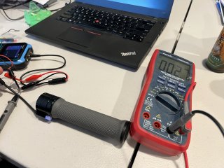
With a new controller, the display turned on. I then confirmed the controller could be re-flashed to the Nilsson firmware v1.5 to use the BBS-FW software tool (and made a donation for his work) and did this all successfully. When connected to a PC, the BBS-FW reads firmware v1.5 and can read/write motor parameters. The battery is putting out 58v fully charged, which I verified with a multimeter at the TX90 connector and is within 0.2V of what the display shows when powered on now.

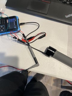
We cannot get the motor to turn using the throttle under any circumstance or configuration setting. The bike is on a stand, and I'm going to pull the motor itself and confirm it's not burnt up next, but have no indication that's an issue.

For the life of me, I cannot figure out why the motor won't turn. The kid denies doing anything else other than wrapping cables, but anything is possible with a teen ;). I've also disconnected all sensors except throttle with no luck and bypassed the display using the programming cable, which also did not work.

What am I missing, and where should I look at next? We're stumped and any assistance would be appreciated.
 
No, it did not after installing new controller before flashing (more detail below).

Motor core windings tested at ~0.1ohms across all 3 terminals and does not smell or look burnt.

The controller was an Amazon unit that was marked 1000W but only 48V. When it turned on, I got a 10H code that wouldn't clear. Research indicated that's a common issue, and also a 52V pack could cause issues with a 48V controller. I also wasn't able to load the prior config from the BBSHD using the BBS-FW Tool. Some research led me to conclude the firmware may be the issue, which is why I flashed to BBS FW 1.5 after confirming the controller was upgradeable. The reflash completed successfully.

The 10H code cleared, and it's currently running the config it had on it that worked great for over a year. I also disabled the speed sensor parameter to ensure it wasn't that (the speed sensor is working and lights up when magnet passes by).

I'm totally stumped. I do have a motor stator and control board that worked when it was removed and am thinking about swapping. It was a delicate job to remove the rotor when the shaft broke and I gave up trying to remove it for the night. The display also is new and labeled an 860c, replacing the cut-cable 850c. I don't think its the battery because I'm seeing 58V.
 
I don't know exactly how this ysstem is wired, but if the actual throttle signal and voltage are inside the cable that was cut, if either was shorted to the battery voltages that go to the display, the throttle coulc've been damaged. Even if it isn't directly shorted if the TX/RX between display/controller were shorted to the battery voltage, and if the chip(s) thsoe go to are powered by the same 5v that the throttle and/or pas are, the chip(s) could've been internally shorted and sent too high a voltage to throttle/pas/etc and damaged them.


Alternately if the brake sensor inputs on the controller are being triggered for wahtever reason, those would also prevent operation.
 
I think you’re right on the throttle. I tried testing it using a 3.3v output from a Temu oscilloscope and verified with the multimeter.

The throttle shows no voltage change throughout its range and just sits at (edit) 2.7 millivolts (not volts) regardless of position - wasn’t paying attention to auto ranging meter.

Is 3V enough to test with?
 

Attachments

  • IMG_8386.jpeg
    IMG_8386.jpeg
    3.2 MB · Views: 5
  • IMG_8385.jpeg
    IMG_8385.jpeg
    1.9 MB · Views: 5
Last edited:
Update: it was the throttle! Thank you very much amberwolf!

I found the old throttle in the junk drawer. Old throttle showed a range of voltages throughout its movement. Threw it on, connected everything, and we’ve got movement.
 
Thought I'd quickly summarize symptoms if this happens to anyone else.

My kid accidentally cut the main wire harness of a bafang bbshd wrapping cables. He must have caused a short with the high-power battery wire in it. Symptoms were dead display and nothing worked.

I tested for battery power at the connector coming off the motor and saw 52V. Jumpering the green connector using a Bafang USB adapter and testing throttle did not work. A new display also did not work, so we got a new controller (I didn't bench-test the old controller, but it was at least 4 years old with hard use). After a new controller, the display powered up as normal, but no motor functions worked. The throttle, which has a blue light to indicate on, showed it was getting power.

Bench testing the throttle revealed that it wasn't working - the potentiometer was not potenti-ing or whatever. Reinstalling old throttle made it work fine.

I think the cut in the wire caused the 52V hot wire to fry everything, an expensive lesson.
 
Bench testing the throttle revealed that it wasn't working - the potentiometer was not potenti-ing or whatever. Reinstalling old throttle made it work fine.
FWIW, the throttle on these is a hall sensor, which runs on 5v. Much more than that on any pin and POOF.

A potentiometer (pot) is just a variable resistor, and could probably have handled the voltage. They do make pot throttles, like Magura and Domino, but as long as nobody cuts the wires you shouldn't need one. ;) (and you'd have to do some other work to adapt the system to the pot type).

I think the cut in the wire caused the 52V hot wire to fry everything, an expensive lesson.
It's not uncommon, though the damage usually occurs at the axle wiring on a hubmotor, most often from a crash or a torque-arm failure (or improper installation). This wiring also contains battery-voltage stuff on the phase wires, and 5v stuff on the hall wires.

It's a serious design flaw of many systems (most ebike stuff, whether OEM, DIY kit, or aftermarket) that incompatible voltages are placed in the same cable with no protection against a short like this.

What *could* be done to protect against the case of your type of incident is to have the battery voltage and KSI line from/to the controller inside a braided shield that is system ground, with a fast-acting fuse at both controller for battery source and inside display for KSI source, so that if it's cut into, it will probably short the ground shield against the battery voltage or KSI line and blow the fuse, disconnecting the battery voltage *before* it can short to anything else in the cable.

Additionally, place the TX/RX (5v level lines) and any other lines that aren't batery voltage level or ground inside a separate braided shield that is also grounded, and install a 1kohm - 10kohm resistor in series of each of those lines at both display end and controller end, so that if there is a cut and those are shorted to ground or each other (rather than battery) they'll not be able to source or sink enough current at 5v to damage the transceivers. And if the battery/KSI lines do get cut and somehow don't short to their own groudned braid to blow the fuse, they will then be shorted against the grounded braid outside the TX/RX/5v-level lines and blow the fuse then, beofre the cut proceeds into those low voltage lines and kills something there.

But this adds cost to the wiring and parts list for controllers and displays...so it won't happen.


Even better would be if they'd use optically-sent data, then there'd be no low voltage wiring to short out.

Next best would be using optocouplers for transcievers, which would help at least partially isolate the rest of the low voltage system against battery voltage intrusion. Diodes on the VCC inputs to the transcievers *and* between tranceivers and the internal data lines would further isolate things.

Probably other ways I haven't thought of in my allotted 5 minutes of rambling (and 20 minutes of editing to make it readable). :lol:
 
Thought I'd quickly summarize symptoms if this happens to anyone else.
Great outcome, and great follow-up and summary. Sometimes these threads are like reading a mystery novel with the last page torn out. I hope the kid treats you like the king of the castle, for a day or two at least.
 
FWIW, the throttle on these is a hall sensor, which runs on 5v. Much more than that on any pin and POOF.
You are absolutely correct, and fully agree with separating the 52v from the rest of the low-voltage stuff. Fast moving magic pixies don't play well with the slow moving magic pixies.

He bought a Lekkie Pacemaker throttle when we swapped frames and was sad to see it get fried. I may take it apart, see if I can get one of the Honeywell hall sensors for a few bucks, and try bodging it together.

 
You are absolutely correct, and fully agree with separating the 52v from the rest of the low-voltage stuff. Fast moving magic pixies don't play well with the slow moving magic pixies.
No, they don't: the pixie dust gets all mixed up and you get to find out why matter and antimatter aren't supposed to touch. :lol:


He bought a Lekkie Pacemaker throttle when we swapped frames and was sad to see it get fried. I may take it apart, see if I can get one of the Honeywell hall sensors for a few bucks, and try bodging it together.
When you take it apart, make sure you reference some of the throttle repair threads for images of what ot expect isnide. (there are some pics in the thread you link, but they don't appear to show the original position of some of the parts, just full assembly and full disassembly states). The springs on some of these things are practically impossible to get back in there correctly if you didn't see how they were in there to start with. Also, the magnets inside need to stay in the exact configuration they started in, and some of them are not glued in, just held in by the casing being snapped together. If they fall out, get moved or flipped or anything the throttle won't operate correctly or at all, and it is a PITA to figure out the fix. :(

The SS49E or a clone thereof is the most common type used in these; I think the Allegro 13xx is another series I've seen used, but don't remmeber which one.

But because each sensor is designed to respond to a different field, you'll need to use the same kind that is already used in there if you want it to respond the way it did originally. If a sufficiently different one is used, it may not even work as a throttle; the voltage output could be offset too far one way or the other and either never reach full throttle or never turn off.
 
Back
Top