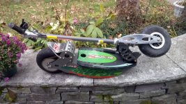
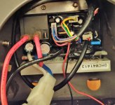
I was recently given a Bladez XTR SE scooter. When I turned on the switch, the red LED came on, then flashed briefly and went out. I removed the batteries and charged one, but the other one was completely dead. I had another one from a UPS, so I charged it and swapped it in. I'm getting 26+V from the pack, so I connected it back up. However, I noticed that the red wire is no longer connected to the controller and is just hanging. Does anyone have a wiring diagram for the controller? I figured I should confirm all the connections before proceeding...
Heyyy, what a coincidence, I recently got the same scooter! Surprised to see someone from Maine has one, it’s a company from Florida and most buyers were from the area.
The red light flashing can indicate incorrect wiring to the relay, I had the same problem too (I think I messed it up at first), I just kept changing the wires until it worked, there’s only a few possible combinations of red wires on the three pins; I can send a picture of my wiring in few hours. It will also give a flashing red light if the throttle is depressed when turning on, or if the motor thermometer is disconnected/damaged.
Just a heads up, the scooter uses a TON of current and the original motor seems kinda crap in my experience. Mine burned out, and I suspect the wires used in the coil were too thin for the current drawn, causing them to melt insulation and create a short. A UPS battery will not work well in the scooter as those are meant for lower current, and will degrade very quickly. I replaced my batteries with equivalent spec lead acid batteries, and the range is now a quarter of what it was after 10 cycles or so. It should really be converted to lithium, but it’s hard to find drop in lithium batteries that fit and can provide the 25 amps continuous the scooter needs.
The company BladeZ is still in business, however I believe they’re only selling old stock now. All parts are really expensive and you can only order over the phone. Support from the company is poor and once again is only possible over the phone. Their email and online help isn’t in service from my experience.
If you end up needing a part in the future, I can help you find parts that will work for cheaper.
Here’s a link to my thread on the scooter:
My ~12 year old Electric Scooter Project - BladeZ XTR SE