BLDC Brain

hardym

100 W
Joined
Jun 7, 2008
Messages
109
Location
San Diego, CA
Very impressed with Jeremys ongoing Simple BLDC project at http://endless-sphere.com/forums/viewtopic.php?f=2&t=23350

However, I think that there is a better brain for a controller than a MC33033. I believe that all of the functionality can be better implemented in a flexible CPU architecture rather than burned into a fixed silicon implementation.

The features that could be better implemented in SW are
- soft start
- adjustable current limit
- hall event filtering
- output data stream and data logging
- timing tuning

There have been several threads that have postulated how this could work, instead of commenting, I built one. I used a PIC16F690. I utilized the internal PWM for the throttle control, a comparator for the current limit (~10uS response), and the pin interrupt architecture for the hall sensor inputs. The rest is pretty straight forward PIC stuff.

The software and hardware will be updated and posted into this top topic posting. I've yet to go for a test drive -- a test ride is worth a thousand calculations.

Here is a video of the brain in action. It is hacked into a 12 FET controller (not an infineon), and testing with a bench power supply.

My hope is that this can one day be used with Jeremys awesome simple brawn project:

Video:
[youtube]kOyKSl5j4UQ[/youtube]

Software is written in Microchip's Free C (Hi-Tech C), using the standard libraries.
(I had to post in PDF as .c and .txt attachments are not allowed
Verison 1.0 Initial release
Version 1.2 improved soft start, improved display, speedomoter gauge.
View attachment main-brain.1.2.pdf


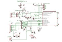
Schematic:
V1.1 changes include Hall filtering and extra headers for Jeremys brawn.
V1.2 adds more filtering needed on throttle inputs and current sensor inputs
file.php

Mark.
e-brain-schematicv1.2.jpg

As always, suggestions encouraged!

The Tin Man,
 
Nice work!

Great to see someone who's hacked into an existing controller like this. I thought of doing it the other way around, using the front end from an existing controller and hooking it to a new power stage, but never got around to actually trying it.

If your brain can output 6 phase drive signals (three high side, three low side) at standard logic levels and accept a current limit input as a small voltage direct from the shunt then it should interface up pretty easily to the simple controller power board. The power board would also need a 12V supply for the driver chips and DC DC converters than run the high side.

Any idea how fast it will run? For a hub motor it may not need to have an electrical rpm of more than around 500Hz or so, but for some of the faster motors it would need to be capable of running at a bit over 1KHz.

Jeremy
 
I am going to try to keep the first posting with the latest software and hardware.

Yes, this brain drives a ‘standard’ e-bike BLDC motor with 120 degree hall sensors, and 6 fets drivers (3 high w/PWM and 3 low).

The hardware was rather simple, as you can see in the schematic. Halls inputs are set for interrupts that change the FET outputs. PWM is running at 25KHz and uses the built-in PIC PWM. Current Sense is set to a .1V internal comparator.

There is a data output to a serial debugging display at 9600 bps. A textural display is very helpful in debugging. Example display is a parallax 16x2 LCD (mouser).

The software is getting more complicated as it progresses. The main loop of the software sets up the system, then loops reading the throttle inputs to set PWM duty cycle, and output debug display. Interrupts do all the leg work. I’m still working on better comments and code cleanup. All my previous PIC work has been with the CCS C compiler, this is my first use of the free Microchip Hi-Tech compiler, which is more flexible, but has less built-in stuff.

This reference is a great list of what a smart controller brain needs to do:
http://www.infineon.com/dgdl/AP0802...b0af6&fileId=db3a304412b407950112b40c61bd0b0f

One insight from the Infineon manual is how to detect noisy or bad hall readings. When the halls change, the latest hall reading is compared to the “expected” hall reading to determine if it is likely correct. If it's not correct, the brain turns off all FET power and re-reads the halls to get a better reading. This is helping, but there are still some bad hall readings at higher power level and high rotation speeds, 25 mph +.

Hopefully this can be cleaned up with better wiring, and hall input filtering. Curious if anyone has any suggestions here.

No road test just yet.
Mark
 
Lay the thing out so that it has a compatible pinout for use with Jeremys' power board...


I'd bring the hall signals in through a resistor with a filter cap to ground. Feed that into a schmidt trigger buffer (like a 74xx14 hex inverter). Even better, opto isolate them. The hall signals are basically a fairly high impedance signal running parallel to a cable carrying potentially 100+ amp pulses... lots to go wrong with induced currents, coupling, general electro-badness.
 
Have you also looked at the Microchip AN1175 and AN970? (970 uses a very nice virtual neutral point for sensorless commutation).

I'm a fan of sensorless controllers, cooked a few hall sensors.
 
Brain is getting smarter. Version 1.2 of software and hardware is posted at the top of the thread. HW includes connector for the Simple BLDC controller. SW includes better display, MPH, softstart, and current limit comparitor.

All I have is a sensored 1000W wheel motor. Since the sensor are already in there, I can't see advantages of attempting sensorless commutation.

I went for a test drive with this smarter brain on a 12 FET box, 48V lipos. The power was considerably higher than with the original brain, but there was a noticable growl, much more that I've heard before. I think I have all the Halls and Phases correct, as it has lots of power. This is perhaps to the higher allowed amperage. This brain allows up to 100% pwm duty cycle. (The MC33033 also allows 100% duty cycle.) The orginal 12Fet controller brain only allowed about 50% duty cycle -- maybe this is common on e-bikes?

To reduce the growl at 100%PWM, I was thinking that the PWM on EACH hall cycle could be raised slowly, say over a couple of cycles. There is more work to be done here.

And I think I need a bigger brawn board.
Mark.
 
hardym said:
IOne insight from the Infineon manual is how to detect noisy or bad hall readings. When the halls change, the latest hall reading is compared to the “expected” hall reading to determine if it is likely correct. If it's not correct, the brain turns off all FET power and re-reads the halls to get a better reading. This is helping, but there are still some bad hall readings at higher power level and high rotation speeds, 25 mph +.

Hopefully this can be cleaned up with better wiring, and hall input filtering. Curious if anyone has any suggestions here.
Mark

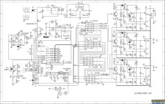
In looking at the schematic for the early Shenzhen controllers, they use a bigger filter cap on the hall inputs. Those controllers also had a limitation in how fast they could commutate, but I don't think it was because of the hall signal filters. They used 0.01uf caps and 3.3k resistors to make the input filter.Shenzhen schematic.jpg
 
Nice project, Mark.

I wonder if the best technique might be to use the halls for starting only and then transition to sensorless control. The Hall devices are not necessarily in exactly the right place. Back EMF readings should give a more accurate timing. I seem to recall that the sensorless transition comes before the commutation transition so there is time for good filtering.

Halls also occasionally fail so being less dependent on them is a benefit.
 
Thanks for the schematic. The schematic FET driver circuits are nearly identical to the old controller box that I hacked into, but my controller CPU is much different, it’s a SunPlusIT chip.

Without this schematic, I could not have understood the high side driver. The high side FET driver voltage is supplied by a charge pump using the 47uF capacitor. The original controller brain used PWM on the high side, which is necessary for the charge pump. (My replacement brain also puts PWM on the high side, but that was by accident.)

The original controller PWM frequency was measured about 15KHz; my PWM brain has been working at 19K and 25K. From this new understanding of high-side drivers, I’m now thinking that 1) the PWM frequency needs to be matched to the high-side charge pump, and 2) use of 100% duty cycle, may be a problem, that 90% may be has high as can be used considering the charge-pump drive circuitry.

Other notes of interest from the schematic is that the schematic output FETs are not identical. This is interesting because there is such thing as a 9-FET Infineon controller (unbalanced quantity of FETs). (See thread http://endless-sphere.com/forums/viewtopic.php?f=2&t=24836). Looking at the 9-FET controller pics, two FETs are used on the low side, and one on the high side. This probably means that the overall current thru the non-PWM low side is higher than the PWM high-side (assuming that there is a limit to less than 100% PWM duty cycle).

So, the takeaway is the duty cycle should be limited to, say, 90% in the brain. 100% PWM may cause charge pump failure with high side FET pinch-off (and may cause the “growl”).

All this is educational, but the target use of this brain is Jeremys brawn driver which has a much simpler FET driver with just a few parts: an IE1212 DC/DC, and an NCP5181 driver. For comparison, the schematic driver uses 20+ parts on each phase.

Other schematic observations:
PWM gate drive modulation is done in external logic. RC2 is the PWM output of a 16F77 which is used to PWM throttle thru the NOR gates. It looks like they had no trust in all this so they added another gate driver cutoff using RB1 (a bit paranoid?)

The 16F77 doesn’t have an internal comparator. The schematic’s external op-amp pair for separate current sense interrupts and current level detection is nice, and probably better than my plan of using an internal PIC comparator with a fixed .1V voltage. If a current shunt is necessary in a controller brain, may as well collect current usage data, which can be used to determine battery state of charge.
 
hardym said:
If a current shunt is necessary in a controller brain, may as well collect current usage data, which can be used to determine battery state of charge.

This would be assuming that the battery was 100% charged at the beginning of use, right? Otherwise, it could mislead the user into thinking there is more capacity than truly available. Am I missing something? As the rest of your analysis is quite above my understanding, I could be misinterpretting your above statement.

Thank you for taking the time to disect your chinese controller and add to Jeremy's outstanding accomplishment! :mrgreen:
 
hardym said:
The original controller PWM frequency was measured about 15KHz; my PWM brain has been working at 19K and 25K. From this new understanding of high-side drivers, I’m now thinking that 1) the PWM frequency needs to be matched to the high-side charge pump, and 2) use of 100% duty cycle, may be a problem, that 90% may be has high as can be used considering the charge-pump drive circuitry.

Other notes of interest from the schematic is that the schematic output FETs are not identical. This is interesting because there is such thing as a 9-FET Infineon controller (unbalanced quantity of FETs). (See thread http://endless-sphere.com/forums/viewtopic.php?f=2&t=24836). Looking at the 9-FET controller pics, two FETs are used on the low side, and one on the high side. This probably means that the overall current thru the non-PWM low side is higher than the PWM high-side (assuming that there is a limit to less than 100% PWM duty cycle).

When you approach 100% duty cycle, presumably the motor will be turning, so the phase commutation will allow the bootstrap circuit to continue working. If the rotor was locked and you hit 100%, then there would be a problem.

Since cheap controllers don't use synchronous rectification, the low side FETs will be working as freewheel diodes when PWM is going on. The body diodes in the FETs have a lot more voltage drop than the a FET that's switched on, so the low side FETs can get hotter than the high side ones during partial duty cycle. I think that's the reason for the 2 low 1 high configuration.

All controllers should have current measuring! You're absolutely right that the processor could keep track of amp-hours without any additional hardware. You could at least drive some sort of fuel gauge display with it. This is way better than watching the pack voltage. Commercial fuel gauge chips like the TI BQ2xxx series can use a pack low voltage event to self calibrate the gauge. Most laptop packs have something like this.
 
hardym,

What are the possibly options with this brain?
I’m on the hunt for variable regen and cruise :)

~KF
 
Kingfish: With regard to regeneration, I have no idea how it works in a BLDC controller. If anyone has any tech notes on this, it would be much appreciated. Cruize is no problem, as the controller already calculates speed. Need to think about handlebar display, buttons and a cruize control button.

fechter: thanks for the notes. Agree need to add current measuring.

number1cruncher: I think with voltage measuring on Li packs, that full charge can easily be detected: LiFeP04 cells charge up to between 3.6 and 4.2V per cell after a charge. But this 'surface charge' is lost in a few seconds of use down to 3.2V/cell. So a voltage detection could tell if the pack was fully charged. Also, most small EVs are fully charged each time, it's a safe guess.

Mark
 
hardym said:
Kingfish: With regard to regeneration, I have no idea how it works in a BLDC controller. If anyone has any tech notes on this, it would be much appreciated. Cruize is no problem, as the controller already calculates speed. Need to think about handlebar display, buttons and a cruize control button.

<snip>
Mark

Hey Mark :)

I have spent the afternoon and evening scouring over my downloads of the last year regarding Regen Braking. I have two code sources; the first was high-level and I really don’t think it would help at all, so I tender the second as being informative as well as providing a potential solution.

We’ve seen this reference before: Design and Prototyping Methods for Brushless Motors and Motor Control by Shane Colton – June 2010

  1. Please go to Page 110 – 7 Appendices
    This is a good spot to begin reading. I am trying to keep in perspective Jeremy’s design. There has been various discussion about how to optimize Regen Braking; I understand enough to get lost and up to my ears in alligators so I must defer to those vastly more capable to explain it. Regardless, Shane’s approach figures close to the existing Braun Circuit design.
  2. On Page 118 – 7.1.6 Controlling the Half-Bridge
    Three states are discussed: High-Side, Low-Side, and Freewheeling (Float).
  3. On Page 122 the Microprocessor is identified as MSP430F2274. Digikey lists these as Texas Instruments IC MCU 16BIT 32K FLASH 38-TSSOP.
  4. On Page 125 7.3 Source Code of Case Study Controller
  5. And on Page 129 the Regen Braking Range is defined programmatically.
The question that begs to mind is can we get the most regen with this dead-simple Braun Circuit, or would full-bridge rectification work better? It’s a little OT but relative to a programming solution.

Now I realize the chip you’ve chosen is the PIC 8-Bit, and the code example above is for a TI 16-Bit. It’s just a pointer and if it helps you gain illumination on how to implement Regen then I’ve done my job. I just wish I could do more to support you, programmatically-speaking, however C++ is not my strong suit. Although I'm pretty good with crayons... :)

Best, KF
 
With regard to regen. I read thru the links and found a few more on line. The implementation is still a bit of a mystery.
My best guess is this: When you want regen and the wheels are moving in the forward direction, Simply apply a small pwm (say 1-5%) to the controller in the REVERSE commuation sequence.

Again, this is just a guess. I can give this a try in a few days.... unless someone suspects that this will cause a smoke effect.
Mark.
 
Awesome job! I would write some code and help out but I havn't written for a PIC in a long time now. Maybe I can port the design over to an MSP430 for kicks? I've never fully understood regen on a hubmotor myself, considering there is only so much BEMF to use to charge. In general regen isn't terribly effective in the end anyway. Something to play with down the line though. Very exciting with all the BLDC work!
 
IIRC regen is done by momentarily shorting and then releasing each winding; the shorting provides some of the braking, and then the resulting voltage spike of the now-open coil provides more of the braking as the FETs body diodes pass that voltage back to the battery.

Exactly how this is implemented in the controller I don't know. :(
 
amberwolf said:
IIRC regen is done by momentarily shorting and then releasing each winding; the shorting provides some of the braking, and then the resulting voltage spike of the now-open coil provides more of the braking as the FETs body diodes pass that voltage back to the battery.

Exactly how this is implemented in the controller I don't know. :(

Awesome input AW, Sweet new green username too... :mrgreen:
 
Here’s another way to look at the problem:

Motor in Generator mode, take the output, rectify and regulate the load (presumably through switching FETs) back to the battery. To imagine how this could be accomplished the maximum possible regen, I reviewed wind turbine controller circuits. They are interesting reads if nothing else:


I don’t know if these circuits are easily adaptable to any controller or if it would require additional circuitry, but from a hardware engineering perspective it sure looks dead-simple.

It would also seem to me that electric braking is accomplished by counter-phasing; overtly switching at nullifying or even reversing shifts which naturally implies heat-loading.

Perhaps it is possible to borrow the dummy load concept and when the batteries are at their limit then the resistor bank takes the load. This would imply a significant heatsink associated with the casing. But then it seems like an advantageous feature to dump heat out of the controller cum brake rather than have induction motor heat.

I’m just thinking out loud here… :)
Regeneratively, KF
 
Kingfish said:
Perhaps it is possible to borrow the dummy load concept and when the batteries are at their limit then the resistor bank takes the load. This would imply a significant heatsink associated with the casing. But then it seems like an advantageous feature to dump heat out of the controller cum brake rather than have induction motor heat.
This has been done here on ES at least once using Plug Braking with coils of wire wrapped around the bike frame itself as a heatsink. ;)
 
What's hard about simply running the motor in generator mode is that you don't necessarily generate enough bemf to get a charge voltage higher than your pack voltage. Especially for overvolters.
 
grindz145 said:
What's hard about simply running the motor in generator mode is that you don't necessarily generate enough bemf to get a charge voltage higher than your pack voltage. Especially for overvolters.

The PWM works against the inductance of the motor to up convert the BEMF voltage (as it down converts when driving).
 
Back
Top