hardym
100 W
Jeremy started this concept of a Simple BLDC Controller brain in this thread:
http://endless-sphere.com/forums/viewtopic.php?f=2&t=23350
And he published some nice schematics using a MC33033 chip as the brain.
I thought the 'Simple' part of the concept could be improved with a better CPU controlled brain. That thread was:
http://endless-sphere.com/forums/viewtopic.php?f=2&t=24519
With some help, we finally figured out regeneration and some details of PIC operations.
So, I thought I'd combine both threads like an Oreo into a this brain-and-brawn thread.
The newest ideas are to
- start with a box.
- combine both the brain and brawn in the box, add external user inteface and programming if you like.
- switching power supply to save precious power.
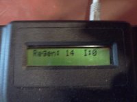
- regeneration. Every body wants regen. Newest concept is to use a left brake switch to actuate the regen, then twist the right-hand throttle to increase level of regen. Should be pretty cool. Will need a test drive.
The parts are just starting to come together. Heres a video of the first 'turn':
http://www.youtube.com/watch?v=857sK4UeP4U
(Thanks miles for fixing this link")
[youtube]857sK4UeP4U[/youtube]
The latest Processor is now a 16F886. It should have ample capacity and IO lines.
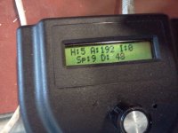
The software for this chip is abit different from the previous 690 brain. This code uses the same free Hi-Tech C compiler. The regen part exceeds the chip's stack if you use the free compiler. I'll keep the latest -886 SW udpated in this first posting. I've included a HMI menu system from an old project but none of the EEPROM configuation has been worked.
View attachment main-brain.zip
View attachment 1
This is mostly Jeremys brawn schematic. Some changes include a 12 v switcher powersupply based on LM5008, A 5v shunt regulator for the Brain, a dual op amp for current interrupt comparator and current sense amp, and caps on the inputs to the NCP5181 drivers -- There was some noise from the switcher that needed to be dampened.
.
The brain schematic is still in progress. Regen mostly works, but current sense is not connected
http://endless-sphere.com/forums/viewtopic.php?f=2&t=23350
And he published some nice schematics using a MC33033 chip as the brain.
I thought the 'Simple' part of the concept could be improved with a better CPU controlled brain. That thread was:
http://endless-sphere.com/forums/viewtopic.php?f=2&t=24519
With some help, we finally figured out regeneration and some details of PIC operations.
So, I thought I'd combine both threads like an Oreo into a this brain-and-brawn thread.
The newest ideas are to
- start with a box.
- combine both the brain and brawn in the box, add external user inteface and programming if you like.
- switching power supply to save precious power.
- regeneration. Every body wants regen. Newest concept is to use a left brake switch to actuate the regen, then twist the right-hand throttle to increase level of regen. Should be pretty cool. Will need a test drive.
The parts are just starting to come together. Heres a video of the first 'turn':
http://www.youtube.com/watch?v=857sK4UeP4U
(Thanks miles for fixing this link
[youtube]857sK4UeP4U[/youtube]
The latest Processor is now a 16F886. It should have ample capacity and IO lines.
The software for this chip is abit different from the previous 690 brain. This code uses the same free Hi-Tech C compiler. The regen part exceeds the chip's stack if you use the free compiler. I'll keep the latest -886 SW udpated in this first posting. I've included a HMI menu system from an old project but none of the EEPROM configuation has been worked.
View attachment main-brain.zip
View attachment 1
This is mostly Jeremys brawn schematic. Some changes include a 12 v switcher powersupply based on LM5008, A 5v shunt regulator for the Brain, a dual op amp for current interrupt comparator and current sense amp, and caps on the inputs to the NCP5181 drivers -- There was some noise from the switcher that needed to be dampened.
.
The brain schematic is still in progress. Regen mostly works, but current sense is not connected