EcoForumZ
10 W
- Joined
- May 20, 2008
- Messages
- 83
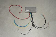
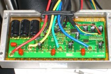
Anybody out there have the wiring diagram for the BMC 35a 24v - 48v controller to a BMC Hub motor? The 25a BMC controller I got with the motor works perfectly and the wires match up color for color but the 35a controller wires do not match up 100%. One of the throttle wires is a different color but the other two wires are red and black so I assume the other wire green and white go togather.
Below is how I have the wires now. The motor sounds like it is running in reverse or in neutral.
3 large wires from motor
Green - Green
Blue - Blue
Yellow - Yellow
5 small wires from motor
BrownishRed - Red
Black - Black
Green - Green
Yellow - Yellow
Blue - Blue
Wires from controller to throttle
Red - Red
Black - Black
Update: Correct wiring diagram is listed below. "Thanks fechter!"
Motor Controller
Phase wires:
Blue Green
Green
Green Blue
Blue
Yellow Yellow
Hall sensors:
Blue Yellow
Green Green
Green
Yellow Blue
Blue
Red Red
Red
Black Black[/quote]
Green - White
View attachment 2


Below is how I have the wires now. The motor sounds like it is running in reverse or in neutral.
3 large wires from motor
Green - Green
Blue - Blue
Yellow - Yellow
5 small wires from motor
BrownishRed - Red
Black - Black
Green - Green
Yellow - Yellow
Blue - Blue
Wires from controller to throttle
Red - Red
Black - Black
Update: Correct wiring diagram is listed below. "Thanks fechter!"
Motor
Phase wires:
Blue
Green
Yellow
Hall sensors:
Blue
Green
Yellow
Red
Black
Green - White
View attachment 2


