BobCs emax scooter thread

good news and bad news...... The PCBs have arrived - good
they're wrong & pretty useless - bad. That's 40 quid I won't see again.
To save others from making the same mistake.... here is the part of the datasheet telling you what pin does what
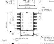
ixysdata.JPG
I thought that was a 'top' view of the module. It isn't, it's a bottom view (with its legs in the air)
@rse
Now re-laying out the board. I could get it remade with top and bottom layers swapped, but the SMD zeners would be wrong and the package data forever wrong, so am fixing it properly....

PS anybody want 5 coasters........
 
argh,

Hey Bob that is frustrating, you need me to pony up for some of that £40 lessen the frustration?

Am working on some designs for battery holders for macallister 36v ones which can be plastic printed based on the charger dock, so that i can use them on the bikes.

Bit frustrating as i started with sketchup, but there is a difference between a poly mesh and nurbs solid based system which i didnt know before starting. Has just used fusion 360 which is autodesks offering, very much similar to inventor so not hard for me to pickup and refine the model.

Got a mate with access to some nice tools, cnc lathes, 3d printers etc. could be good for making a few rc gearbox reductions.
 
Very kind Andy, no I screwed up & £40 is not too bad...
I just fixed the design & resent so I guess we'll see it in a couple of weeks
I must spend a litle time getting the yellow bike going - it is all but there and performance looks very promising. I'll put my drainpipe battery on it when I get the charge controller/ balancer going.
 
bobc said:
PS anybody want 5 coasters........
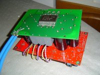
Oh man, I've done that more times than I care to admit... Those tooling fees start to add up when you keep making iterations hey.
 
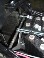
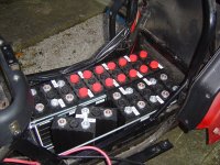
Now it's cold and dark, I've taken the scooter to bits to fit the batteries properly and make the balancer/charge controller work. Last night I made 19 balance wires & I spent a couple of days last week messing with M6 studding and laser cut stainless battery clamping plates. It looks as though 26 cells will go in pretty snugly (leaving much too little room for my fat banana fingers to wield the spanner..)
I need to make a proper charger connection (bought some mini andersons) and to mount a couple of switches (one is "charge enable" and the other is "balance enable"). I'd also like to mount an LED voltmeter (the dash display is wrong range & rarely visible). I bought an ebay voltmeter but it is too small for me to read now...
The power board for the lebowski controller is substantially together now, ready to start testing. I'm fairly unsatisfied with the high current motor connections on the control board (to the hall current sensors) but if I keep my fingers crossed they might be OK. The connection method I put on the power board actually looks pretty good - I'll have to get some pictures...
 
A couple of pictures of the "proper" battery fitment. The laser cut 3mm stainless plates cost £12 and will hold the 26off 40Ah LiFePO4 prismatics - that gets me 40Ah at about 80V.
DSC01670.JPG
DSC01671.JPG
 
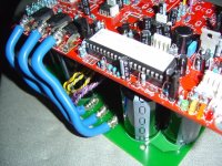
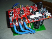
Progress with power wiring on lebowski based inverter.
I'm fairly happy with the way the big wires are connected to the PCB - lacing with TC wire onto a big SMD pad looks as though it will work and it's relatively easy to make a neat job.
DSC01674.JPG
DSC01673.JPG
DSC01672.JPG
 
FWIW I can compare LiFePO4 prismatic and 18650 cell based solutions in this vehicle.
LiFePO4 - "80V" solution is 40Ah, cost me £1040. Weight is 36.2kg
18650 - "80V" solution would be 105Ah and cost me about £1750. Weight would be 33kg

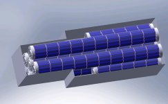
A more interesting 18650 solution would be 70Ah, similar cost to the LiFePO4 system but 2/3 the weight and 75% more capacity.

The LiFePO4 stack is a less 'risky' assembly, in that I have high confidence that it will operate as intended for the lifetime of the batteries, an 18650 buildup is more effort in a relatively untested assembly, but if I were starting again I would probably go that way; it's hard to argue with the numbers.
emax105ah.jpg
 
Very nice fitment of the 40 Ah packs! Still looking at about 3 kWh? The higher top speed on the E-max will be a pleasent change - you'll have no trouble hitting 90 km/h with that voltage.

I'm working on pouch cell packs which would offer about 180 Wh/kg, I reckon I can get the range up to about 110 km per charge with them, but seriously, who would ever ride a scooter that far in one sitting? My arse is sore after about 30 km!
 
yeah 3.3kWh by my reckoning; my only concern is that I may use a lot more power with the higher top speed and start to hit capacity problems - it seems to average 1.6kW with the 30mph limit.
Like you, I can't imagine using up 105Ah in one sitting..... But a big + with the higher capacity is the reduction in the discharge cycle. My commute takes me to about 70% to 80% DOD (more as it gets colder) (40Ah at 18s, 57V) which is a bit more than I would like.
PS just looked at your battery build thread - most interesting - that's where the Wh/kg comes from I guess: the LiFePO4 look like 97, the 18650 stack 240
 
This was my concern too, thinking that when I upgrade to the sevcon and get it going faster I may need some aero tweaks like a windshield and a fairing.

That's rendering of the 18650's looks awesome. Still waiting on my 120 ohm resistors to terminate the canbus as I cant get to the internal one in the sevcon throught the ampseal loom I bought. Next year is gonna be a good year for these scooters.
 
bobc said:
yeah 3.3kWh by my reckoning; my only concern is that I may use a lot more power with the higher top speed and start to hit capacity problems - it seems to average 1.6kW with the 30mph limit.
Like you, I can't imagine using up 105Ah in one sitting..... But a big + with the higher capacity is the reduction in the discharge cycle. My commute takes me to about 70% to 80% DOD (more as it gets colder) (40Ah at 18s, 57V) which is a bit more than I would like.
PS just looked at your battery build thread - most interesting - that's where the Wh/kg comes from I guess: the LiFePO4 look like 97, the 18650 stack 240

I'm a big fan of the pouch cell and the screw terminal development has opened up a lot of possibilities. I can manage 180 Wh/kg as a built package and still get 10C continuous (20C peaks). Easy 5 kWh in that space.
But it's wasted on a scooter with such a bloody uncomfortable seat :lol:
 
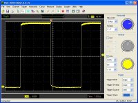
Lebowski's software includes a test 50% output mode
testpwm.jpg
That's on a 35V power supply - it just took a few milliamps
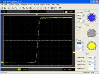
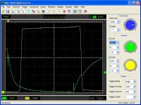
this is the rising edge
rising.jpg
nice, clean, no overshoot. looks like a bit too much dead time
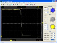
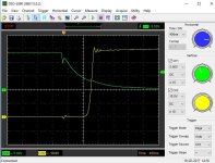
and the falling edge
falling.jpg
still over 1/2 microsecond dead time, also looks clean & well behaved
hipulse.jpg
If we look at gate and drain voltage on the same trace, you can see that above I was mistake assuming dead time when what I could see was the gate charging current.
textbook miller plateau at 4V on the gate.
No "shoot through" apparent or measured on the supply current (just 35mA used at 35V when PWM enabled). actual dead time looks like about 0.8us
 
So looks like a decent test? when are we hooking it up to the hub motor in the chair?

I have now got the 5amp fuses and the 120ohm resistors for the sevcon programming. Will get to test that this week as pips is away at her sisters with the dog and baby. Roll on project time. Tonight is assembling the plastic printer from china.
 
Still getting the gear together to take this further. I've got Andy's (whereswally) spare emax motor wired up, along with its hall sensors.
We tested the hall outputs - 3 open collector operating from 5V supply: so this wires directly to the lebowski hall connector.
The thing I need which I've not got is a suitable throttle, so I just bought a couple of hall throttles from ebay: about £7 and should appear tomorrow. I should be in a position to fire it up then.
I did try the current offset calibration, got a short hum from the motor & a calibration result which was similar on each phase, but reduced every time I did it (I would expect 2500mV to be the offset) ending up near zero(?). And I'd expect the offset to be measured while the inverter was 'off' - no?
Anyway I'll do some checks with the voltmeter when Andy comes round (nothing like having an extra pair of hands & eyes on the job)
With luck we'll get as far as the hall calibration & motor spinning. Perhaps Bas can tell me how low I can take the current setpoint when scaled at 12.5mV/A (200A sensors) - I'd prefer to take the volts up first and then start ramping up the amps....
 
ehm, you're supposed to use option a) in the offset calibration menu first, which sets all to 0 mV. At this point I typically exit the menu as I do not use offset calibration. The offset is the difference to the mid-supply. When you run the calibration the values typically move by 20 to 30 mV.

It should be OK to set it at 5% to 10% of the range for testing, but the offset calibration probably already ran at a higher level (somewhere around 20% but am not sure).

Are 200A sensors not 10mV/A ? Typically the ACS type has +- 2V range... Which ones do you use ?
 
The motor drive is operating at low current and voltage levels, and Bas (lebowski) supporting us with help about the control algorithms/IO/setup/procedures etc. My concern is to not take too many liberties while it's all having the wick turned up, so I'm waiting for a power supply that will give us sensible power limit. We've done tests so far with a 70A breaker and a 30A fuse in line to 50V of RC lipo, but I don't like it. When Ebay does its stuff, we should be able to start getting things warm & scope some proper loaded waveforms.
The battery balancer/charge controller is fully debugged now, ready for proper integration into the bike. Still not decided where I'm going to put the controls & LEDs; I'd like to keep it separate from the controller changes I plan to increase top speed, makes "under the seat" non-ideal...
 
Got a bit of time on this today and it is going nicely now with 50V DC supply.
I was mostly interested in the voltage overshoot when switching, you can see here it looks nicely under control
run50V.JPG
I'll start taking the amps and volts up when I have more eyes on the job (and a thermal camera)
Stone cold so far but only 3 amps and 50V, I'm hoping for 60A and 80V at the end of the day.
 
Hey Bob I was reading the Sevcon manual and I learned that you can go up to 69 volts on the battery. I realise you are building your own controller, but still, I might have to experiment with some more batteries for shits and giggles... and 90 km/h :D
 
Hi Chris,
I have the "proud eagle" & it allegedly maxes out at 63V. I've got 63V of battery on there but no way of defeating the speed limit (29mph). I actually also have a sevcon which should be good for over 100V and I will probably fit that eventually (waiting for Andy to debug the "commissioning procedure"). This development is sort of "plan B"
I would redo it to use for real, the current sensors should be associated with the power electronics, and the control electronics should be SMD and about 1/10 as big...... and probably on the same board. If the IXYS part is reliable (that's the biggest risk with this design, using 100V transistors with a 80V battery) then it's quite a nice size thing for a small motorbike or scooter.
Lebowski's software has some really attractive features for this kind of development - the "hall sensor learning" cuts out a rake of heartaches, the setup is nice and straightforward (control loops etc.) and the fieldweakening performance good and seamless. All the commercial stuff needs fancy pants interfacing and much of the useful stuff is hidden from you to stop tinkerers killing themselves in their commercial machinery. The sevcon looks better than the proud eagle in that respect.
 
Hey Bob, yes haven't worked on the sevcon in weeks, but need to pull my finger out there. Trying to finish of the mpcnc project which will mean I can mill the alu heat sink to cut it down to fit just the controller. Hopefully this year we will get to upgrade both these Emaxs one way or the other. Hopefully catch up soon.
 
Hi Bob,

Any chance you could share some details on the laser cut battery plate parts?
What did you get for your £20 and did you supply the material or was that included?

I'm looking at swapping out my hand cut motor mount with something more accurate (and a bit nicer looking)
 
Back
Top