Build your own CD battery tab welder for about $100.00+-

RLT I finally received my power supply and turned the voltage up to the maximum 15.2 volts and what a difference! I had tried cleaning the batteries before, but now I don't have to do any prep and the welds are solid. I am very happy with my welder now and can confidently build packs thanks for all the help!

------robin
 
Great stuff.

Do you know an online source for nickel connecting tab material, bigger than the really narrow stuff that Sunstone stock, by any chance?

I've spent ages Googling and so far come up with zilch. I can find suitable copper sheet, but am not sure if this will weld easily to the Headway cells or not.

Jeremy

PS: I'm part-way through building a double pulse system, using FETs to switch the current. I'll post details when (if?) I get it to work.
 
did you try getting shim stock from McMaster-Carr. you'll need a sharp set of shears to cut it. it comes in a sheet 6"wide b 25" long. 0.010 would cost $81.00. it also comes in 50" sheets.

http://tinyurl.com/53oz3r

rick
 
Thanks for the link, Rick. I try and see what they charge to ship to the UK.

Jeremy
 
I looked at McMaster again ,a few weeks ago, but wow, that's a lot of money for not a lot of material. Still, after ten or more hours of searching, I haven't found any better deals for small quantities.

A good way to cut any sheet metal (softer than steel, and under about .04") is with a paper cutter... The guillotine type, not the rotary stuff. I've been cutting sheet brass, bronze, silver, gold, copper, aluminum etc. with one I bought from Staples or Office Depot for about $20, for more than 20 years. A lot neater and easier than I can cut with shears for anything over a couple inches wide/long.

Rhoon: Glad you got it working!.

The Molybdenum rod came in today... Well, yesterday, since it is now after midnight. Made up a couple of 'pencils' of it like I did with the elkonite and spent an hour or two experimenting

Yeah, I like it. Another step up in durability like the elkonite was from plain copper. Better quality welds on copper, Great on steel to steel and copper or steel to titanium.

Just in time for building the new battery packs: Will finish running the first 55 cells through the CBAII tomorrow.

LOUSY on nickel though. The moly doesn't stick to the nickel, but the nickel sure sticks to the moly. Even at 12V and single pulse it is unusable on nickel.

But for tabbing with copper, I don't think we are going to find anything better.

I'm thinking of offering some copper covered molybdenum 'pencils' or complete electrode-handpieces for sale at not too outrageous prices. Let me know if you might be interested.

Oh.... I just remembered where I got nickel sheet back in the old days when I was making patterned Damascus for knife blades:.... Let me check.....

Yeah, MUCH Cheaper than McMaster:
http://www.admiralsteel.com/shop/201.html

and you can get smaller pieces if you don't need as much:
http://www.admiralsteel.com/pdf/bladesteel.pdf
About half way down the PDF page, on the left side: 201 nickel.
$4.72 for 12"X6" of .005
$9.62 for 12"X6" of .01
 
wow Admiral Steel is a lot cheaoer than McMaster Carr.

regarless both are mucho cheaper than Sunstone. Sunstone sells 0.25" wide strips 25" long. if i were to buy enough of those to make up a 6" wide strip it would cost $384.00. and that is nly for 0.005" thick and not 0.010".

with the money saved from one batch of tabs you could well afford to buy a good quality paper guillotine or even an inexpensive bench shear for metal.

what usally causes the burr to form when using a paper guillotine type cutter is the sheet being cut does not start to cut immediately but instead is pulled slightly underneath the blade. to stop this movement you could use a piece of flat steel bar and a couple of clamps to hold the work piece.

rick
 
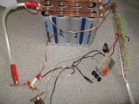
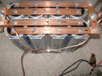
Finally, I finished the welder. The setup is 12Farad power acoustic caps, 24 mosfets irf2804 , 6 mosfet drivers, thick wires gauge 0,3x 555 on a separate sequential timer board so I can set 2 independent pulses and break length. All done with a minimum resistance, as you can see there are huge coper bars.... probably too too low resistance..
So what went wrong?
I charged it to 5V and it did produce a nice 2 pulses as it did before(at that time with only 3 caps from a different maker).
Since I was testing it with this array of new caps on 0.3mm copper strip I needed more power. I changed to my 400W switching power supply . I could start from 14V so I did. After firing the micro switch mounted on the rod I saw a flash of blue light on my super duper power mosfet board.
Gone are all 24 mosfets, too much current. I simply didn't expect the power acoustic to be so powerful.
What next?
If I had more money(already spent over $400!) I would go for even better mosfets. I think that the idea of using a lot of mosfets is right. It all worked, just there where too many caps or too few mosfets.!
I also sourced single 12 inch/ 1/4 dia elkonite rod here in the UK so I was even more ready for copper.
Anyone wants to help to order some mosfets from the usa for me ? This time IRF1324S.
Last time I ordered irf2804 and i ended up paying too much because the very expensive shipping charges and import duty! I ended up paying more than 2x the net price!
Thanks guys! I can pay up front, no problem. Just need somebody from the USA to reship them to the UK. Ideally that you have a paypal.
I would go for 50! IRF1324S from here:
http://www.alliedelec.com/Search/ProductDetail.asp?SKU=273-2073&R=273%2D2073&sid=482394002B4DE17F
Nemo
 

Attachments

  • welder final1.JPG
    welder final1.JPG
    113.4 KB · Views: 5,770
  • welder final2.JPG
    welder final2.JPG
    99.1 KB · Views: 5,766
Howdy nemo,
I've been following this thread for a while now and am very interested in making a tab welder for myself. I've already started gathering parts.

I'd be happy to purchase & reship MOSFETS to you. I've already got a history of selling on eBay and have shipped internationally. Either DigiKey or Mouser would be good sources for them. Their available selection & specs for parts are far better than Allied Electronics (their site needs some work, imo). :)

I'm getting the picture that using a big SCR doesn't give useful control over the energy released from the capacitors. But I've got one incoming from Surplus Sales of Nebraska (nice supplier of surplus industrial gear), a 1kv, 224A puck, for $27! :D
http://www.surplussales.com/

Let me know..
 
Huh i am watching this thread very carefully and nemo i am sorry that you burned mosfets so quick...
Did you check max avalanche energy that your mosfets can take?
Since the resistance of all your copper peaces are so low, the mosfets were taking it all so i advice next time to use a little bit thinner wire or bigger stack of FETs with more avalanche capability...
0.6Joule is value for single pulse if you go with current over 75A per mos, do you know max current when discharging caps without mosfets when shorting them (you have owon so check voltage drop on thick copper wire in capture mode, and check resistance with some big amp PS@10amps or more to find voltage drop relation to calculate cap current discharge).
If you go over few KA then that would explain mos burnout (thick wires).
 
Some of you may already have such knowledge, and I'm sure there's all sorts of other info on these technologies out there, but I found the info behind these links very useful and enlightening (particularly the PDF)…
http://www.powerdesigners.com/InfoWeb/design_center/articles/MOSFETs/mosfets.shtm
http://www.powerdesigners.com/pdf/High%20Efficiency%20Power%20Switches.pdf

I just received the massive "hockey puck" SCR I ordered from Surplus Sales of Nebraska. It's impressive. Tho, after reading the info above, I'm more convinced that a MOSFET/BJT/IGBT switching setup would be far better/precise.

... just wanted to share more info.
 
Pity about the FETs blowing. I suspect it may not have been the peak current that blew them, but might have been a big voltage spike when they turned off. My guess is that even a very small amount of cable inductance might well induce a fairly hefty spike from a FET turning off quickly. Maybe a snubber network across the FETs, or better still a fast voltage clamp, might just stop a repeat performance.

Jeremy
 
I'll post more photos and schematics.I can't afford this to loose mosfets again and maybe we together can find the solution to reliable mosfet super-switch.
I used 24 irf2804 (up to 40V) datasheet here: http://pdf1.alldatasheet.com/datasheet-pdf/view/92816/IRF/IRF2804.html
Thinking of using IRF1324S-7PPBF (24V) datasheet: http://pdf1.alldatasheet.com/datasheet-pdf/view/190937/IRF/IRF1324S-7PPBF.html
With crappy caps(3x 1.5F) it didn't blow and I produced a nice 2 pulses. I could just weld nickel 0.3mm thick to nickel.
But 8 CAPS joined by thick copper bars was TOOOOOOOOO MUCH for my poor expensive 24 IRF2804. To drive them I use 6 TC4422 9A drivers! Each for 4 mosfets, all very short thick wires and each gate had a separate 10 ohm resistor.
The question is. Would you use 24 IRF1324 with 1mohm Rdon and good for up to 24V and better current handling capability ? Or go for 50? IRF2804 or even 50 IRF1324?
I'll measure current with a small piece of 2.5mm2 wire instead of a mosfet switch, look at my owon and calculate the current from a resistance and voltage produced.... tomorrow. I'll also put here some of my super secret photos of the mosfet switch so it can be improved and copied. It's too late to do anything today. N.
 
I'm pretty sure that, even with those big caps, you couldn't get more than about 1000 to 1500 amps. The limit is going to be the total circuit resistance and the system voltage.

I doubt that the total discharge path resistance, including the FETs, cables, bolted connections, cap ESR and most of all, the resistance of the electrode/workpiece connection, would be less than about 0.01 ohm.

With your capacitors charged to 15 volts, the maximum current with a 0.01 ohm discharge path total resistance, would be 1500 amps. This peak current would drop very quickly, as the system voltage drops and the workpiece heats up. FETs are also self-protecting against over-current to some extent, as their Rdson increases as they get warm from self-heating.

On the other hand, switching off a few hundred amps will give rise to voltage spikes from the cable inductance that could quite easily get up to a few hundred volts. It only takes a very short high voltage spike to punch through a FET and kill it. Your description of the way your FETs failed sounds exactly like a high voltage event to me.

Using a very fast transient suppressor across the FET bank, rated at a voltage that's over the system operating voltage but below the FET max Vds, would almost certainly prevent this. A typical fast TS will turn on in about a nS and will handle very high peak power levels, typically a few hundred watts for a very short time.

Jeremy
 
could you suggest a suitable transient suppressor? please?

would those of us using SCRs also benefit from some protection of a TVS?

rick
 
I have used the P6KE series before with good results (on another project). Pick a voltage that is higher than the maximum working voltage and below the maximum Vds of the FETs. The data sheet is here: http://www.ortodoxism.ro/datasheets/comchip/P6KE7.5C.pdf These should be readily available from the bigger component suppliers - I can buy them on line here in the UK cheaply enough.

There's no need for them with an SCR, as the SCR cannot turn off once triggered, so cannot generate big voltage spikes. The problem only arises when a bank of FETs switches a very large current off, very quickly.

Jeremy
 
I have found some info about TVS (transient voltage suppressor) here: http://www.microsemi.com/micnotes/125.pdf
Some more info here: http://www.littelfuse.com/data/en/Application_Notes/an9768.pdf
I would go for couple of parallel 5kp20a zenner diodes.
http://www.sage.lunarpages.net/wfc/ds/5kp20a.pdf

Since there is a quite difference in between working voltage and Vc clamping voltage(it will not allow to go over this voltage, it clamps most power at this value) I can't use IRF1324S(good only up to 24V max) but again IRF2804 (good up to 40V). With IRF1324S working voltage with a protection using TVS is about 13v because Vc is already about 23V!
I hope I got this right. How to connect them? Parallel to a mosfet bank and cathode to + side? Is unidirectional protection enough? Or do I have to go bidirectional and use 2 diodes?
 
That TranZorb TVS will be fine - you only really need one. Fit it across the FET bank, as close to the FETs as possible and between them and the heavy cables. The idea is to make sure that there is very little inductance between the FETs and the TVS. If you have an arrangement of cables that gives inductance at both side of your FET bank, then fitting a TVS at each end would make sense.

Your best bet would be to look at using FETs with a higher Vds rating, to give yourself some headroom for the TVS to work. As you've noted, the TVS clamp voltage will rise during a heavy current spike, with a 20V device clamping at about 30V at peak current.

I don't think you need to worry about reverse protection, as both the TVS, and the integral FET body diode, will conduct and limit reverse voltage peaks to a few volts.

Jeremy
 
could a TVS also be used for arc suppresion across a relay or switch contact? i use a relay to switch between the taps of a dual speed Crystalyte hub motor and i would like to quench the arc.

if the answer is yes i may start a separate thread.

rick
 
To be honest, Rick, I'm not sure that a TVS would help with arc suppression. I guess it might reduce the peak voltage that initiates the arc, but whether or not this is really beneficial I don't know. I guess it wouldn't hurt to try it, perhaps just on one phase at first so you could see any difference (assuming you can see the contacts). You would need a bidirectional TVS though.

Jeremy
 
Finally got my nickel sheet from Admiral Steel. They were out of stock on the .01 thickness, and didn't see fit to let me know about it until I asked after a couple of weeks of waiting with no delivery and no notice. So, I told them to send the .005 instead. About a week later, I finally got it. (I still want to try the .01 thickness, but that will have to wait.)

It welds just as well as the strip from Sunstone, and with the paper cutter as I mentioned up above a few posts, you can easily and neatly cut any width of strip you need. Other than the delay I'm very pleased with using the stuff from Admiral.
---------------------------------------------------------------------
And after welding several hundred tabs of both nickel and copper, I've decided to stick with using nickel, despite its somewhat lesser electrical efficiency. Getting good, strong, durable welds on copper is problematic with my setup. You guys experimenting with FETS and other things to give you more control over your pulses might eventually get it perfected, but I'm just not happy with the consistency .

For one thing, the extra energy that I have to use to weld copper to the batteries I'm working with is just more than I feel safe using... If electrode tip pressure is just slightly too light, the weld is either just a weak thin halo... if it is significantly too light, I have literally blasted holes in the battery 'can'.

So, I've disconnected all of the stuff of my dual pulse setup and am using 14.6V single pulse through my '5F' and '1.5F' audio caps in parallel. With that, nickel strips and regular copper electrodes, I get strong, consistent welds with no worries about blowing holes through battery cans.

If I ever need to do spot welding on stuff that is heavier than batteries, I'll hook the dual pulse stuff back up, plug in the molybdenum or elkonite electrodes and use it: My test welds on mechanical components, including exotic materials are quite satisfactory.
 
Thank you ( RTL) for sharing all the information here again! A great sum-up. I suspected that copper welding is hard. I'm still going for a mosfet switch. This time with a protection against high voltage spikes.
I have also ELKONITE 1/4inch rod on the way to me. When the welder is finished I'll post my findings too. I'm also getting nickel of both thickness from admiral, thanks to a kind sole on the opposite side of the ocean.Cheers to everyone. N.
 
I think I'll stick to nickel strip as well, maybe just using bigger tabs to make up for the slightly greater resistive losses. Thanks for the update on Admiral, if I can't find a source here in the UK I will try ordering from them.

Nemo, can I ask where you found elkonite rod over here, please? I've been scouring the web, searching ebay etc but 1/4" rod seems had to come by.

On the topic of transient suppression, I found a couple of metal oxide transient suppressors that look pretty good. Check out the RA series from Littelfuse. The size 16 ones I have will tolerate a 4500 amp transient, turn on in about 1nS and are bidirectional. They also have a reasonably close clamp voltage/trigger voltage ratio. There are some details in this hefty PDF file: http://www.prime-electronics.com.au/datasheets/data/Littlefuse/Littelfuse Suppression Products.pdf Check out the RA series.

Jeremy
 
Here is the source.(after a long search)
http://www.futurealloys.co.uk had 1 off cut rod about 12 inch long 1/4inch dia that I'm getting. I'm not sure but they might be able to order more. They should have my cheque by now and hopefully will post it soon to me. So pleeeeeeeeease don't take that one. It was less than £30 shipped. Not cheap but that's life.
 
Thanks for that, Nemo. Don't worry, I won't contact them just yet!

I've been looking at alternatives to nickel for making battery connection straps. Copper looks best (next to silver, which is just OTT). I've done a comparative list of the relative resistivity of some metals we may be able to get hold of relatively easily. It's pretty interesting to see how they compare:

Copper = 1 (as a baseline reference, no units, anything over one is a worse conductor than copper)

Aluminium = 1.59

Zinc = 3.48

Nickel = 4.12

Brass = 4.12

Tin = 6.73

Nickel looks like a pretty lousy choice, particularly as it's got the same conductivity as brass. Aluminium looks to be a pretty good choice, except that I've no idea as to how easy it would be to spot weld thin aluminium sheet as inter-cell connection straps. I'd hazard a guess that it's pretty tricky to weld.

I get the feeling that welding copper sheet is not too easy with a home made welder, so am tempted to try something else. Brass sheet is very easy to buy and is also cheap. Given that it's about the same conductivity as nickel, I wonder why it's not used?

Jeremy
 
Jeremy,
I think that there is a reason for not using copper alloys when battery pack making. Firstly you need a better electrodes (more expensive) and they need to be resharpened. If made of copper this is easy, if made of elkonite it's harder because of the hardness of the alloy. Then the welder is more complicated and more expensive. With nickel you probably get better welds more consistently.People who asked for better current capability of packs are mostly modelers and some electric car makers (my guess). And they solder and this is not an ideal situation for the packs life.(too much heat)
Dewalt uses thicker( 0.25mm) nickel in the 36V packs. Curiously enough there are approximately 2 spot welds that are not very good in nearly every 10 cell dewalt pack I saw!
But I'm getting this thickness from the USA now and if my attempt to spot weld copper to A123 fail I'll use nickel .

One good news is that ELKONITE is still available at http://www.futurealloys.co.uk. Ask for 1/4inch dia, 12 inch rod. Cheers, Nemo
 
Back
Top