Build your own CD battery tab welder for about $100.00+-

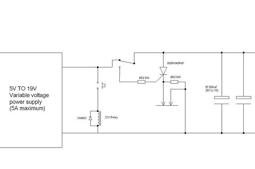
If anyone in the UK is looking for thyristors to build a CD welder, I will have a few spare in a day or two. I've just bought a small job lot of fairly big ones, type 180RKI40PbF, with the following ratings:

Voltage, Vrrm:400V
Current, It av:180A
Current, It rms:285A
Current, Itsm:4000A
Voltage, Vgt:2.0V
Current, Igt:150mA

It's the Itsm rating that's important for a CD welder. These are pretty good at 4000 amps.

I'll sell the surplus ones at the same price as I paid for them, but it probably only makes sense to post them to people in the UK really. The price each will be around £4.50, plus postage (postage will probably be around £1.50 maximum, I think). I should have about eight spare ones, if all goes to plan. First come, first served, PM me if you're interested, rather than clog the forum.

Jeremy

PS: These things are BIG, the thread on the stud is 3/4" UNF.............

[edited to include spec sheet details and part number]
 
A quick update on my welder project.

I built up the capacitor bank today - boy am I fed up with drilling holes in copper busbars, copper is nasty stuff to drill, especially if you don't use any lubricant and the drill sticks (as it will, and did - I have a nice cut on my arm where the bit of broken drill flew off............).

Here's a picture of the capacitor bank, with the big thyristor bolted on.

2578760948_b02e5802fd.jpg


Those capacitors are 97,000uF, 20V, low ESR ones from switch mode power supplies. To give the picture scale, the capacitors are 3" diameter and about 4 1/2" tall. The thyristor has a 3/4" UNF thread and is about 1 1/2" across the flats of the nut.

There are fifteen capacitors hooked together in parallel, so I'm hopeful that 1.455 F of decent quality capacitors will be enough to weld up to perhaps 10 thou nickel tabs.

Jeremy
 
Wow, very neat and nice work!
Reminds me of something ! :)
As for copper drilling I used a sharp (brand new) set of cobalt plated drills and hand held battery powered drill. Went ok, didn't loose a single drill mainly because I set a moderate torque.It did help to prevent a drill damage after drill jam. Update on my welder: I have a spare set of mosfets now! A transient voltage suppressor protective diodes (like zenner) 5KP20A. Nickel tabs 0.125mm and 0.250mm! Elkonite rod as I wrote earlier.
I may try to get it working again next weekend. And keep the fingers crossed for me so I don't burn the mosfets again! Cheers!
 
It works!

My very first weld turned out to be perfect, so I'm well chuffed. Here are some pictures of my welder, together with a wiring diagram. The capacitor bank is as shown in the post above and is contained within the wooden base box.

2618305146_c0d75de45e.jpg

Side view, showing the spring loaded sliding pillar that carries the electrodes. The arm pushes the pillar down, then tensions a spring to provide consistent electrode pressure. The firing button is on the end of the operating arm.

2617482299_8cf441ffcf.jpg

Front view, showing the pair of electrodes fitted to the composite arm. They are free to slide up and down slightly, but are held by a bit of rubber mat at the top so that the pressure is applied evenly. The box on the left is the variable voltage power supply.

2617482903_3f95c72c62.jpg

Close up of the electrodes, showing how they are held in place. I cut slots in the 1/4" copper bar and soldered in strips of 3/4" x 1/8" copper strip, at right angles, to make the connections.

Jeremy

[Next instalment in following post]
 
Here's the wiring diagram:

2617536945_32d2cca992.jpg


2618106641_75312e878c.jpg

I used a relay, connected to the firing button, to control the thyristor. This disconnects the power supply whilst the button is pressed, and also triggers the thyristor using the charge on the main capacitor bank. This is a bit kinder on the power supply, as it doesn't get shorted out by the thyristor, plus it also makes sure that the thyristor gets turned off at the end of the discharge. The 8R2 resistor across the electrodes is there to allow the capacitor bank to be discharged at the end of use, without the need to produce a weld. It makes no appreciable difference to the weld current, but draws enough current to hold the thyristor on if it's triggered with no work piece present, so discharging the pack.

2618305866_39b89cf11e.jpg


Close up of the operating arm and tension spring. The arm first pivots down, pushing the pillar down via the nylon rubber block. This puts the electrodes in contact with the cell. Further movement of the arm tensions the spring at the rear, sliding the arm rear end up the slot. This applies fairly consistent pressure to the electrodes, for good weld consistency.

So far I've done a few test pieces and found the weld to be superb. I'm using some 6 thou (0.15mm) nickel sheet and haven't had any problems with electrodes sticking or burning.

Next task - weld up 64 Headway cells into a 16S, 4P pack................

Jeremy

(PS: I still have some of those big thyristors spare if anyone wants one)
 
Thanks Tyler.

The grey square tubing is some pultruded fibreglass that I had lying around. It was great for this job, as not only is it non-conducting, but it also happened to be a nice sliding fit into ordinary 2" x 2" x 1/8" wall alloy box section. The only snag with the stuff is that the dust from cutting and drilling it is evil - it's little tiny bits of sharp glass fibre that really irritates.

Hopefully I'll have some pictures of the first welded up back cells soon. I just need to finish off the jig I'm making to hold the cells in position.

Jeremy
 
Thanks RLT.

Another update. I've been making loads of test welds to try and find out the best settings, both for electrode pressure and also for voltage. I've found out a couple of interesting things, plus managed to blow up a thyristor (through my own error). Luckily I have a few spare.

I had to modify the base board to make it stiffer, as the pillar was leaning over slightly when under pressure, causing the electrodes to move. Adding a bit of 5/8" thick board on top of the base fixed that.

Welding voltage is highly dependent on the thickness of the metal under the electrode. Welding two bits of nickel together on top of a bit of hardwood only needs about 9 or 10 volts. Welding the same two bits of nickel together on a block of aluminium needs about 16 volts. It seems that the heat sink effect really makes an appreciable difference.

Electrode pressure setting is also very dependent on the rigidity of the material being welded. A lot more pressure is required welding on to something very solid and stiff than when welding thin sheet on top of a block of wood. The electrode pressure is easy to adjust, using the threaded bar that pre-tensions the spring at the back.

Finally, the reason I blew a thyristor was down to finger trouble. I accidentally triggered the thyristor before I'd pushed the electrodes down. Because of the 8.2 ohm discharge resistor I added as a safety measure, the thyristor latched on. The resistor takes a long time to discharge the capacitor bank, around 12 seconds or so, so as the electrodes hit the work piece there was a big bang and a flash. The very high Di/Dt blew the thyristor. I may modify the design to get rid of this discharge resistor and fit another, higher value, one across the capacitor bank directly. This would eliminate this slight risk.

All told I'm quite pleased with the way it's worked out. Judging by the quality of the welds I can't see any obvious reason to use anything more sophisticated. This really simple capacitor discharge system seems to work as well as anyone could want, at least for welding nickel tabs.

Jeremy
 
Awesome.

One minor Q:

Are the arm and deck sized to fit all the req'd cells you will be welding? Depending on your pack layout, it may need a deeper/taller/wider arrangement?
 
It's pretty much sized for 38120 cells, with the electrodes set at the right height for those. It could be made taller, by adding a spacer under the pillar and can effectively be made shorter by adding spacers under the cells.

The width of the pack is limited to about twice the arm length, which means I can't weld into the centre of a pack that's more than about 10" wide. If the pack is assembled in rows, then a much wider pack could be built, as the arm only needs to reach to each cell.

The length of the pack is only limited by the amount of support available. The present deck is about a foot wide, but it'd be easy to add supports either side.

One limitation for smaller cells is the electrode spacing. At the moment, this is just under 1/2", which is fine for the big end caps on 38120 cells, but a bit too big for the smaller caps on things like A123 cells. I guess I could either make the spacing a bit tighter if I needed to weld up smaller cells, or else I could perhaps switch to a "ring and centre point" type setup, although this would only do one weld per fire, rather than two.

I just finished welding up the first 12 cells and all seems to have gone OK. Despite making lots of practice welds, I still found that I had to make a lot of adjustments to get good welds on the cells. The biggest change was the need to apply much more electrode pressure, which has meant adding a big rubber pad for the arm to rest on. The adjustable power supply seems redundant, as it turns out that about 13V is the best voltage, which means a lead acid battery on charge works OK as a power source (and doesn't get as warm as my small power supply).

Jeremy
 
whats the stuff that battery tabs are made out of? i tried some stainless steel sheet at work and i couldn't solder to it?
 
Pure Nickel.
A great job Jeremy with the welder.
I have 10pcs of surge protective diodes 5KP20A. If you need any let me know! The specs looks promising, hope they protect mine welder when finished.
 
Thanks Nemo.

Monster,

The tab material is pure nickel sheet, 0.15mm thick. It welds very well to the battery ends, which I think are made from stainless steel, and can be soldered reasonably easily using a hot iron and the right solder.

I believe that nickel is the material most commonly used for weld-on tabs, although if you want better conductivity copper can be used. The problem with using copper is that it's a complete pig to weld, and needs special electrodes. To all intents and purposes nickel is the best all round material, as far as I know.

Stainless wouldn't be much good for a couple of reasons. As you've discovered, it's difficult to solder and needs a special flux and a very hot iron to have any chance of success. Secondly, it's not a very good conductor, so you need a thicker tab to get the same resistance as a nickel one.

The only problem with nickel is buying the stuff here in the UK. I was going to order some from the US, when a roll of pure, lab grade, BDH nickel sheet came up on ebay for a good price (list price for the roll was well over £100, I got it for £19.50 inc postage).

I've now welded 24 cells together, just another 40 to go.....................

Jeremy
 
I'm BACK!!!!!!!!!
PARTIAL SUCCESS WITH MOSFET BASED WELDER AND MORE INFO ABOUT THE PROBLEMS WITH A HUGE INDUCTIVE CURRENT FLOWING BACK TO MOSFETS

Today I repaired my humble welder!!!
24 mosfets in, few hours of soldering!
and 5 ! protective diodes in parallel , each able to sink 400A/10ms. I tested them and they don't allow voltage to go over about 23V! (like zenner diodes)
http://www.datasheetcatalog.org/datasheet/GeneralSemiconductor/mXuwywt.pdf

Few welds went very well. At 11V I was able to spot weld 0.25mm nickel to nickel and it held well, I made holes when taking them apart.
...and.... suddenly the 24 mosfet switch were conducting full time! not like before 2 precise bursts of energy flowing into a welding place.
Strange, oh my god.... did I destroyed the fets AGAIN? (strange , last time they actually went open, not shorted)
Than it came into my mind that maybe just the diodes that will not allow reverse polarity shock wave to destroy the fets ARE SHORTED!
So I cut them off and yes 3 out of 5 were DEAD!
I put 7 remaining in parallel. After 3 welds THEY GOT SHORTED/destroyed AGAIN !
They were cheap and they saved my fets!
Result: about 5 great welds with a precision time mosfet control!
No more welds after the protective diodes were removed.
I need BETTER and bigger protective diodes! Or something else. This welder is a monster!

I need to sink more than 1000A to protect the mosfets.
Any suggestions?
 
You're getting there, Nemo!

At least we now know that the high voltage spikes created at turn off were most probably the reason your FETs blew originally, plus we know that the FETs really can take the abuse of handling hundreds of amps for a short time.

The problem now is the ability of the transient voltage suppressors to take the power in the turn off spike. My guess is that there is a matching problem here, with the real-world turn on voltage of the individual Tranzorbs being slightly different from each other. This would lead to one or two hogging the current in the spike, so causing the overload.

You may be better off by trying to find some suitable varistors. I have some 56V holding voltage ones here in my junk box that are good for 4500 amps max, they trigger at 68 to 75V though, so are too high a voltage for your FETs, I guess. There are lower voltage ones about though, see here: http://production.littelfuse.com/data/en/Data_Sheets/Littelfuse_MOV_RA.pdf for example. These things are very fast and perhaps more robust than the Tranzorbs, as they aren't semiconductor junctions.

Good luck!

Jeremy
 
I'll do a research and try them. It was quite interesting to see that big inductance voltage spike being cut at exactly 24V by the diodes (curve on the oscilloscope).
5 in parallel failed at about 8V, 7 in parallel at 11V. Never all of them!.So your theory is correct.Some were taking a bigger portion of the current. On the internet I read how to parallel them. One has to choose the ones with the same characteristics.
Test them on the oscilloscope with a moderate current. I'll do that and use about 10 to 20! They should hold then. They are about 10 pounds for 20. Unless I found a huge varistor! Thanks for all the help and encouragement here!.
 
You're doing a great job, Nemo.

I'm pretty sure those varistors I have would be OK, as they will handle 4500 amp spikes at the cut off voltage, which is a great deal more than the Transorbs.

Having now made quite a lot of welds with my thyristor system I can appreciate the advantage that a well-controlled FET switched system might give.

The thyristor works fine, but does require a bit of careful adjustment. The voltage needs to be tweaked up slightly as the electrodes get warm, plus I get the occasional duff weld on one electrode (randomly) that I think might be due to the cleanliness of the surfaces (I'm lightly abrading the surfaces with a Scotchbrite pad, then degreasing them). It may be that using a double pulse would better clean the weld area before the main welding pulse, which might then mean that the main weld pulse power could be reduced a bit. At the moment, there is a fine line on my system between enough voltage (charge) to get a good weld and either too much voltage that leads to a burnt weld or not enough voltage that leads to a poor weld.

I'm wondering if there is a better way to make sure that most of the weld current goes through the weld area. Looking at the design of the tabs on some NiMH cells, I've noticed that they all have a slot up the centre. It looks as if this slot is a way to ensure that most of the weld current goes down through the tab to the cell cap, then back up through the weld on the other side, so reducing the cross-current that must flow directly across a plain tab. Does anyone know if this is really why these tabs have slots in them?

If this is a technique that produces better welds, then I might change to using several parallel tabs to get the same effect, with one electrode on each tab.

Jeremy
 
I think that this might be the case.(don't know for sure!)It also can make welding easier since the extra flexibility of the metal.
back to the welder: I think I have found suitable varistor at last! here:http://cgi.ebay.co.uk/24Z50-100J-MOV-Metal-Oxide-Varistor-Harris-10-LOT_W0QQitemZ180256188837QQihZ008QQcategoryZ73144QQcmdZViewItemQQ_trksidZp1742.m153.l1262
This is a biggest one (20mm disk) one can get, to my knowledge. I'll use 10! Max clamping voltage is 43V(should probably do) It is a littlefuse component and I located the datasheet here:http://www.prime-electronics.com.au/datasheets/data/Littlefuse/Littelfuse%20Suppression%20Products.pdf
It's 9MB! And you have to search through the pdf to find it.
PEAK CURRENT 8 x 20μs is 2000A each. Don't know what to think about this.

This surelly will be more robust protection than suppressor diode.
The seller ships very quickly. I know this because the suppressor diodes were from him.
Don't know if I should combine the two types of protection, probably not.
Soon I'll be doing more tests, and if everything goes well I'll share my little know-how.
 
They look like they may do the job, Nemo. From what I can gather these MOV varistors are much more robust than the tranzorb type suppressors, yet are still plenty fast enough to protect your FETs.

I'm wondering about switching from my big thyristor to FETs, as I have a couple of bags of cheap IRFB4110 FETs that I got via ebay. As these have a pretty good high voltage rating, plus as I have a few of the big V68RA16 varistors which should be OK to protect them, I might give it a go and see what happens.

The other option I have is to split my capacitor bank in two and use two thyristors, triggered sequentially. I'm not sure if it's worth the hassle of doing this though, or whether I should just get on a build the rest of my battery pack with the rig as it stands.

Jeremy
 
I'm really sorry that you guys are having all these problems.

Since I took off my higher voltage caps and the dual pulse setup; (just using the 5F and the 1.5F audio caps in parallel, @ 14.5V), and decided to stick with nickel, I've done well over 3,000 individual tab welds with no significant problems. The only time that there is any problem is if I either get a weak weld because I didn't wait the 1.5 - 2.5 seconds it takes my caps to charge fully, or if I get sloppy and my electrode pressure is too light, and I get an arc... and even the arcs aren't too bad at the lower voltage, unlike the 'plasma blasts' I got with too light of pressure with the higher voltage setup.

It is great that you guys are trying to refine your stuff to equal the professional equipment; I'm following your progress with great interest, and would be thrilled if you can build a Unitek equivalent for 1/10th the cost.

But if just building battery packs is the goal... Well,.....My basic, sloppy, crude setup is working even better than I hoped for when I first got started on this stuff last November, and I see no need to refine it any further for putting together a few battery packs.

It is the ONE thing that has been working well AND consistently in my e-Bike project (and life in general) the last few months.
 
There is an additional advantage of having a welder that can shut off the current after the weld is done.( rather than just leaving it on until the caps are discharged). Your caps are recharged much more quickly ! The welding takes shorter time (safer for the cells).More control. Pre-weld cleans they say... Coper welding? A cool feature.
I hope that I will be able to weld 3 times more conductive coper to coper or coper to nickel. I also don't need to go as high as 14V with nickel. When using mosfets one can afford to parallel more caps and get higher amps and use shorter impulse.
On the contrary the welder is mode difficult to make, mosfets are expensive one also need mosfet drivers,timing board, protective circuitry.
If you are having a great success with a cheaper setup than good for you.
I started the mosfet welder. Now I have to make it work .
 
Well, that's what I get for being lazy and not setting it up so that the power supply doesn't shut down during the weld as I intended to do months ago:

A week or so ago, after a few hours of near constant welding, the two power transistors blew on the Pyramid 12A 12V power supply I was using to charge my caps. The amazing thing was that the last weld I intended to do was the one where they blew!.

Fortunately, the replacement transistors only cost $1.69 each at Digikey: http://search.digikey.com/scripts/DkSearch/dksus.dll?Detail?name=497-2612-5-ND

To prevent that from happening again, not only did I put in a solid relay to shut off the AC power to the PS when I step on the switch, I put a CPU fan over the transistor's external heat sink, ad one inside the case to help keep things cooler. I probably could have just used the foot switch's N.C. section to switch the PS power directly, but just to be safe and sure, I used it to activate a solid state relay that fits nicely in the in the PS case.
PSfan.jpg
The two Alkaline C cells are for energizing the SSR., although it can be powered by a 'wall wart' as well:
PSrelay.jpg
Set up with a coax power plug so I can use whichever I want .

I also got some .01 nickel sheet from Admiral Steel. I think it will be better for making heavy duty, high current battery packs than the .005 stuff we usually use. Unfortunately it doesn't weld quite well enough at the 14.5V that is the maximum I can get with my normal setup, (Nearly, but not quite as much penetration as I'd like) so I'm going to have to get out the lab power supply and try it between 16-17V. Hopefully that will be enough; otherwise I'll have to dig out the higher voltage setup. I'll let you know how that turns out in the next few days.
 
That's pretty much how I've set mine up - the power supply is disconnected from the caps for as long as the button is pressed.

Not only does this show a bit of mercy on the power supply, but it also stops the thyristor staying latched on with just the power supply current going through it at the end of the weld. I've no idea if this helps any, but I like the idea of not shorting the supply. Here's the circuit for my set up:

2618106641_75312e878c.jpg


The same relay contacts that switch the supply off trigger the thyristor on, using the power in the capacitor bank, so no extra power supply/batteries are needed, just a single resistor to limit the gate current to a safe value. The thyristor I have needs a fairly hefty gate current to make it switch very quickly, hence the 8.2 ohm resistor, which allows over an amp of gate current initially, to get a hard turn on.

The second 8.2 ohm resistor shown across the electrodes has been removed, as it tended to allow the thyristor to fire and then hold the thyristor on if the button was pressed accidentally without the electrodes being in contact with anything. This caused me to blow a thyristor in a shower of sparks, as I lowered the electrodes without realising the thyristor was already turned on..............

Jeremy
 
Back
Top