Hello friends, I was reading this whole thread and based on my humble electronics knowledge I may comment about some posts;
I am totally new at this forum, and I don't want to contradict anyone in here, my mere intention is to bring some light over the project, and try to make it better.
Reading the datasheet of the SCR SCS230S, I verified that this SCR needs between 100 and 120mA at the gate, with a maximum of 3V between Cathode and Gate. The polarity of such trigger current is (+) positive to the gate in reference to the Cathode. I've seen some drawings on posts with this polarity reversed.
I also want to detail a little bit about the fact that once you trigger the SCR gate, it is self-driven. You don't need to pull a big current at the gate for a fast trigger, even a small current (within the datasheet requirements) will create the self-driven effect. The SCR will supply itself with the necessary current at the gate to self-sustain, until the current is zero (short circuit across Anode & Cathode or an interruption of the current.
Why am I saying this? Because in some posts I saw some circuits prepared to supply a large current (5W resistors in the gate), 8Ω resistors, etc. That is not the issue. You need to supply from 100 to 120mA, no more than 4V between Cathode and Gate (+).
I also saw some posts with relays DPDT and transistors to trigger the SCR, the transistor is not really necessary.
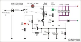
The following design should do a good job, with indicator LEDs presenting the contraption status.

Power Supply can be adjusted or just a power transformer supplying 12-13 VAC 3-5A, rectified by diodes (5A) and feeding the common side of the contacts of the relay. The relay can be any 12-14Vdc coil, automotive relays may be used, however any chosen should stand contact minimum constant current of 5A.
The relay contacts should be SPDT style (Single Pole, Dual Toggle). The normal-closed position will be routed to feed the hungry capacitors side (up side of the drawing), and a tricky 25W car lamp 12V is used between the relay NC and the Capacitors. This lamp (break lamp?) usage in the circuit is to protect the power supply during the very large inrush current the hungry discharged capacitors will suck from it. The lamp will smooth the capacitors charge current.
After a spot welding, the capacitors are discharged and the relay contact returns to NC, the charging current will be huge, since the capacitors offers literally a short circuit. So the lamp will lit bright and the maximum current from the power supply will be 2A (25W / 12V). You may add another lamp in parallel with the first one to double the charging current and shortening the charging time, but be sure the power supply can stand this double current. After the capacitors charge few volts, the lamp will start to dim off, until the capacitors are fully loaded, lamp will be off. You can observe the actual capacitors charging current by the lamp brightness.
Due the DZ1 (9V Zener diode), the Green LED will only lit after the capacitors reach more than 12 to 13Vdc. Green Leds usually lit with more than 3.5 to 4Vdc, plus the 9V zener diode voltage, it requires around 13V to lit the LED. The Green Indicator tells you the Capacitors are really holding a very spike charge.
The Relay Coil is connected along with the capacitors. Using a 12 to 16Vdc relay coil, it will only switch its contact after certain voltage, lets say 8 to 10Vdc, it helps in some way (without more electronics involved) to avoid a false triggering of the SCR with capacitors not yet fully loaded, or in this case, less than 70 to 80% of the charge. Also, the Relay coil holds an inverted Diode in parallel, it may be any 1N4001, 4002, 4007 diode, its function is to protect the coil and the "Weld" switch from spikes caused by Inverted Voltage generated by the relay coil magnetic field collapsing. The "Weld" switch can be anything, considering it will stand the relay coil current.
At the other side of the relay contacts (NO) there is a Red LED and a 1kΩ resistor. This is the WELDING CONTROL ON indicator at the panel (you don't need it, but it can be used). The R1 (39Ω) feeds 14Vdc to the SCR Gate filtering network. The current that crossed R1 will go forward via the 100µF in parallel with the R2 (2kΩ), and rush to ground via Dz2 (3.9V) Zener diode. The Zener will cut any extra voltage, and keep 3.9Vdc that is directly fed to the SCR gate, triggering it for the huge welding current. The 100nF capacitor and the R3 (10kΩ) have the job to keep the SCR gate quiet and free or noises, it is always a good practice to do it, avoiding strange happenings. During the first milliseconds of the relay switched to NO position, the current via R1 will be around 250mA, it will be charging the 100µF capacitor in around 5ms, but at this time the SCR will be already triggered. When the 100µF capacitor is already charged, current will only flows via the R2 2kΩ resistor, it will be very small, and the main function of this resistor is to discharge the 100µF capacitor as soon you release the "WELD" button. It will take around 200ms for the discharge, so, it is fast enough for your next welding. You will need to wait the large caps to charge anyway.
If you don't want to use all the components, you may cut off the Green Led, 150Ω and Dz1, also the Red LED and 1kΩ resistor. You may decide not to use the 100µF capacitor and R2, but then you need to change R1 from 39Ω to 100Ω and it will need to be a 2W resistor, it will warm when you press the "WELD" switch, this is avoided by the use of the 100µF capacitor.
The Dz2 Zener diode needs to be of 0.5W. All other non specified resistors are of ½W, Dz1 can be of 1/4W.
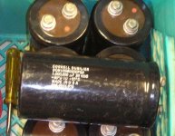
The violet heavy lines around the 4 huge caps and the SCR is the amazing copper heavy bars able to stand the huge peak of current the welding produces.
If after releasing the "WELD" button the LAMP lit bright and doesn't dim off, it means the SCR still conducting, and it may tell you that something is wrong, or the welding was very bad and the capacitors didn't fully discharge, or you released the "WELD" button before the welding current fully discharge the caps (I doubt it), or something else is wrong with the circuit.
The fact that the relay coil is connected to the huge capacitors instead of directly to the 14Vdc supplied by the power source, means that the relay coil will no longer hold the contacts in NO position after the capacitors discharge via the welding procedure. Your finger pressing the "WELD" button may still after the relay turns off, but the relay will not turns on again, since the 25W lamp doesn't allow enough voltage to the coil to energize. If a repeating relay energizing happens, requiring you to remove your finger fast from the "WELD" switch, just insert two or three diodes 1N400x in series with the 'WELDING" switch wire to the relay coil, cathode to the ground direction (toward the switch). It will require the huge caps to acquire more voltage before the relay attempts to attracts again. Other solution is using a relay that requires few Volts more to attracts.

This circuit uses the SCR Cathode tied to ground, negative side of the capacitors. The main idea (and the only one really recommended) is to avoid the SCR to have any positive charge on the Anode until the welding rods are in place, contacting the welding metals. Until that, the SCR will not be able to keep conducting anything, so even if you press the "WELD" button before you position the welding rods, the SCR will not enter in conduction, you will need to press the "WELD" button again. Other than that, the 3-4V necessary to trigger the SCR must be in reference to the cathode. If you use the "wrong" setup as I saw in some posts, with the SCR Anode constantly connected to the positive of the Capacitors, and the Cathode leading to one of the welding rods, may damage the SCR by the jump in voltage between the welding metals, that will comes back to the SCR Cathode and Gate.
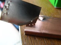
Last thing: I saw several metals with welding tests, and I can't define if both welding rods are being connected to the metal welding strip, or if one rod is being contacting the battery metal part and the other rod contacting the welding strip. Anyway can be done, but talking to the welding people around, they say the correct is both rods contacting the welding strip, never the battery. The reason for that; if the welding went bad, a hole can be done on the surface of the metal where the rods are contacting, in this case, you may damage the battery. Also, according to them, different metals (battery and welding strip) can require you to select which rod you will touch battery or welding strip. I am talking about polarity and electric current direction. This direction of current may move melted metal from battery to the welding strip or vice-versa. You will never want to move metal FROM the battery, it may create a weakness in the battery body at such point, you don't want that.
Of course the design can be upgraded to have a welding current indicator. It might be a simply few coils of wire around one of the rods tick wire, leading to a diode and capacitor, and a voltmeter indicator showing how much this "poor's man current meter" could receive. Few adjustments on such thing can make it a very good indicator to learn how to do a perfect welding. You can use it to learn how much pressure on the rods, etc, based on the feedback of such current indicator.
wagnerlip
 . BTW they accepted a $15 dollar best offer from me
  give it a try. it's a nice module and the spec sheet is readily available. Can handle 250A/ms rise and can handle well a peak current of 7500A to 8500A depending on temperature. I dun think you'll fry this thing ever if you set it up right. and with two you could build a dual pulse welder LOL.


