Build your own CD battery tab welder for about $100.00+-

rkosiorek said:
dbird said:
Hello Everyone:

<snip>

I've ordered my SCR from ebay, an S23AF4B made by IR. Getting datasheets is a challenge, but I found a generic one for this one, 400V, ITSM of 4400A to about 5300A depending on 50/60Hz waveform and whether a voltage is applied afterward or not. It's a hockey puck package. I've figured out how to mount it and how to apply the torque to get something less than the correct mounting pressure. If anyone else needs this info let me know and I'll post it.
<snip>
Thanks,
Dave

Dave,

i was also looking at some hockey pucks. what was stopping me was a simple mount and contact. i'd love to see how you mounted yours. please post pictures. we need more pictures.

rick

Hi Rick:

Haven't built a mount yet, so no pics either. But, here's my concept in words:

The hockey puck contacts are 3/4 inch in diameter, so I plan on using something like a 3/4 inch wide strap on each side to carry the main current in and out. This strap/SCR/strap sandwitch will have a steel plate on each side so the layup will be
steel/strap/SCR/strap/steel . The whole assembly will be bolted together with two nylon (or whatever they are) toilet seat bolts going through holes drilled a little bit on each side of the SCR.

There is a spec on the mounting pressure. 1000 ft-lbs +-10%. That is for thermal conductivity, as I understand, but also affects contact resistance, of course. I don't see the thermal properties as very important because of the low duty cycle. But, I do not want to over torque the assembly. As I understand the mechanics of screws, if I torque each bolt to 500/(12*p) = 2.6 ft-lbs for a 16 tpi 3/8 coarse bolt, if that's what I've got. Then I will have a total of 1000 ft-lbs force not including friction, so I'll probably be OK. I'd sure appreciate it if anyone can critique this calculation and correct if I've screwed it up.

Dave
 
This month I was able to purchase (4) more of those giant 82000μF 100v caps I posted a pic of earlier, so with 6 total I should have just short of half a farad. I am hoping that I can make up for the low capacity with higher volts, but I don't want to reshape the tips after each weld. Has anyone tried the dual-probe hand piece from sunstone? Any idea what the tips are made of?

http://www.sunstonespotwelders.com/spot-welding-accessories-hand-pieces.php

Granted, the $150 price tag blows the budget for a 100 CD welder, but if I can use higher voltages without burning the tips off copper, then I might be interested.

-JD
 
dbird said:
I have read with particular interest the discussions on terminating the pulse before the natural complete RC decay. Maybe I don't understand the operation correctly of the RC/SCR/FET shorting circuit, but here is my problem with it. If the current through the primary SCR is terminated too early, it will be quite large. At that point, the shorting SCR/FET and cap will have to dump the entire primary current at that time in the short transient waveform. The peak current is the killer here, both for the cap and the SCR/FET. And if we wait 'till the primary current is low, we may as well let it go ahead and time out for the full waveform; in other words, if the circuit won't handle the full current, it won't work.

Welcome Dave.

The key to making commutation work (which is what's happening with the second SCR turn of method) is to effectively dump the second current pulse into another capacitor, so reversing the potential across the SCR. Imagine a circuit where the anode of the primary SCR has a capacitor connecting it to the anode of the secondary (commutating) SCR, with the anode of the secondary SCR being connected via a charge-up resistor to the supply. When the primary SCR fires, this capacitor charges up to the supply voltage. If the gate pulse to the primary SCR is very short, then this device can be turned off by firing the secondary SCR. As the secondary SCR fires, it reverse biases the primary SCR via the capacitor, which takes the anode of the primary SCR momentarily below the ground potential, so turning it off. It's not efficient, as the charge resistor for the secondary SCR has to have a low value to ensure that the capacitor can be charged in the time of the shortest pulse width required. It does work though, and is nice and robust.

Jeremy
 
Fritz uses a second method. he has a massive 200A contactor in series with the SCR. turning off the pulse is a simple as timing the contacts to open at the right time to interrupt the flow from the caps to the SCR.

you may have a point about point errosion. and large contactors are not cheap but apparently it works.

it also looks like this project is evolving into something more than a $100 "McGyver style" welder to do up a couple of battery packs. personally i like the increasing complexity and sophistication. when i do build a welder i will have to make some choices. cheap and dirty or a few bells and whistles. but in either case i know it will cost more than $100. in the mean time i find it very educational.

rick
 
dbird said:
The hockey puck contacts are 3/4 inch in diameter, so I plan on using something like a 3/4 inch wide strap on each side to carry the main current in and out. This strap/SCR/strap sandwitch will have a steel plate on each side so the layup will be
steel/strap/SCR/strap/steel . The whole assembly will be bolted together with two nylon (or whatever they are) toilet seat bolts going through holes drilled a little bit on each side of the SCR.

There is a spec on the mounting pressure. 1000 ft-lbs +-10%. That is for thermal conductivity, as I understand, but also affects contact resistance, of course. I don't see the thermal properties as very important because of the low duty cycle. But, I do not want to over torque the assembly. As I understand the mechanics of screws, if I torque each bolt to 500/(12*p) = 2.6 ft-lbs for a 16 tpi 3/8 coarse bolt, if that's what I've got. Then I will have a total of 1000 ft-lbs force not including friction, so I'll probably be OK. I'd sure appreciate it if anyone can critique this calculation and correct if I've screwed it up.

Dave

Dave, i'm just not sure that you can generate that much pressure using those plastic screw. they strip rather easily. i found a couple in my junk drawer and i was able to strip the threads out very easily using fairly light pressure on a small wrench. i think that i will do something like your idea with the straps except that i will make up a couple of 1/4" shoulder washers from some UHMW plastic. those will keep the screws insulated from the stack.

rick
 
Jeremy Harris said:
Welcome Dave.

The key to making commutation work (which is what's happening with the second SCR turn of method) is to effectively dump the second current pulse into another capacitor, so reversing the potential across the SCR. Imagine a circuit where the anode of the primary SCR has a capacitor connecting it to the anode of the secondary (commutating) SCR, with the anode of the secondary SCR being connected via a charge-up resistor to the supply. When the primary SCR fires, this capacitor charges up to the supply voltage. If the gate pulse to the primary SCR is very short, then this device can be turned off by firing the secondary SCR. As the secondary SCR fires, it reverse biases the primary SCR via the capacitor, which takes the anode of the primary SCR momentarily below the ground potential, so turning it off. It's not efficient, as the charge resistor for the secondary SCR has to have a low value to ensure that the capacitor can be charged in the time of the shortest pulse width required. It does work though, and is nice and robust.

Jeremy

Jeremy,

does the commutating SCR have to b the same size and capacity as the firing SCR. or can it be a much smaller unit?

rick
 
rkosiorek said:
Jeremy,

does the commutating SCR have to b the same size and capacity as the firing SCR. or can it be a much smaller unit?

rick

No, it can be a bit smaller. It needs a high peak current rating though, as it needs to take the very short, high current, pulse from the commutating capacitor discharging through it.

The critical bit is choosing the value of the capacitor, to ensure that it can reverse bias the primary SCR for long enough to ensure it turns off, which depends on the device being used and the supply voltage.

Jeremy
 
rkosiorek said:
dbird said:
<snip>
There is a spec on the mounting pressure. 1000 ft-lbs +-10%. That is for thermal conductivity, as I understand, but also affects contact resistance, of course. I don't see the thermal properties as very important because of the low duty cycle. But, I do not want to over torque the assembly. As I understand the mechanics of screws, if I torque each bolt to 500/(12*p) = 2.6 ft-lbs for a 16 tpi 3/8 coarse bolt, if that's what I've got. Then I will have a total of 1000 ft-lbs force not including friction, so I'll probably be OK. I'd sure appreciate it if anyone can critique this calculation and correct if I've screwed it up.

Dave
Dave, i'm just not sure that you can generate that much pressure using those plastic screw. they strip rather easily. i found a couple in my junk drawer and i was able to strip the threads out very easily using fairly light pressure on a small wrench. i think that i will do something like your idea with the straps except that i will make up a couple of 1/4" shoulder washers from some UHMW plastic. those will keep the screws insulated from the stack.

rick

Rick:

Well, 2.6 ft-lbs isn't much, I think, but still you may be right. I plan to use a torque wrench when the time comes to put it together. I hadn't realized that you could get so much force from such a small amount of torque. Guess that's maybe why screws/bolts work so good?

Dave
 
Jeremy Harris said:
rkosiorek said:
Jeremy,

does the commutating SCR have to b the same size and capacity as the firing SCR. or can it be a much smaller unit?

rick

No, it can be a bit smaller. It needs a high peak current rating though, as it needs to take the very short, high current, pulse from the commutating capacitor discharging through it.

The critical bit is choosing the value of the capacitor, to ensure that it can reverse bias the primary SCR for long enough to ensure it turns off, which depends on the device being used and the supply voltage.

Jeremy

Guys:

Well, for my S23AF4B hockey puck, the spec says the turn off time is 15 to 20 us depending on whether it has a feedback diode or not. Don't know what a feedback diode is in this context. Sure wish I still had one of those old GE SCR Application Manuals or whatever it was... But, the spec is for an on current of 300A and the test circuit is not shown so I don't really have much info on how to do this. My first guess is that the cap would have to be in the ball park of C = I *(dt/dV) or, say, using some ball park numbers C = 1000A * (15X10**-6 / 12V) or about 1000 uF. But the ESR would have to be very small too. I think that is a helluva big cap size wise to get low ESR. It don't take much at that current to blow up a cap. Still it might be do-able...

Dave
 
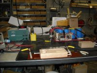
Well, I got my hockey puck yesterday. Jury rigged a mounting for it that approximates what I want to use for when it goes operational. I used the jury rig to do a quick functional test to make sure the SCR was good.

The pic shows pretty much everything of visual interest. There were a couple of problems that popped up.

At first I tried to use the toilet seat nuts that came with the nylon bolts. That didn't work. There was way too much stick-slip when I tightened them to really depend on the torque readings. The steel nut works fine though. The torque readings are smooth, just like when I tighten with all steel parts. BTW, not all TS bolts are nylon, and there seem to be many varieties. I used ones that were made to be tightened by hand (fingers). That works good; much easier than trying to use a screwdriver. They don't come with hex heads. There was no trouble with potential stripping of the threads at any time, although I did not torque them all the way up to 31 inch-lbs each as per spec.

The other "problem" was that it is easy to torque them down and end up with a wedge shape to the two steel straps, probably not a good thing to do. I finger tightened the nuts, miking the separation so that I had a good starting point with the two straps parallel to a few mils. Then I torqued the nuts down just a quarter turn at a time alternating between nuts and re-miking once in a while. That worked good. I didn't go all the way to spec, which was 31 inch-lbs each. That is a maximum allowed. The hockey puck, according to spec (never measured the starting thickness) is .563 total thickness. I stopped tightening at about 25 inch-lbs each when the hockey puck was compressed to .516. Almost 50 mils compression. Sure glad the spec allows the pressure. Squashing semiconductor components really makes me nervous...

Dave
 
i tried an expeiment today using a second SCR to turn off the first. i just used a 10uF capacitor and a 10K variable resistor in the turn off timing circuit. i used it to turn on/off a 12V light bulb powered by a 12V SLA from a UPS.

i found a couple of things. it does work. but sizing of the capacitor and resistor is going to take some juggleing. in order for the turn off SCR to turn off properly the current flowing through the resistor has to be lower than the minimum hold in current of the SCR-meaning a higher value resistor to limit current. yet it also needs to be low enough in value to charge up the capacitor fast enough to be of use. also the capacitor needs to be large enough to hold a sufficient charge to reverse bias the main SCR long enough to turn it off reliably but yet small enough so that it can be charged within the time of the shortest pulse desired from the welder. in the end it may end up that the value of these capacitors and resistors will be different for different SCR's ie. what works in my circuit may not work with your SCRs without some tweaking.

i found some cheap enough 300A hockey pucks on eBay. so i bought them. bought a pair so i can use them in an on/off pair. likely i will use a similar mounting to dbird.

rick
 
dbird,

it may be easier to get less deflection in the steel straps and higher pressure if you drilled the holes for the plastic screws closer together.

rick
 
rkosiorek said:
dbird,

it may be easier to get less deflection in the steel straps and higher pressure if you drilled the holes for the plastic screws closer together.

rick

Hi Rick:

There's essentially no deflection in the steel straps. It's almost all in the SCR. That's why I didn't torque it all the way to up to the max.

Dave
 
oatnet said:
This month I was able to purchase (4) more of those giant 82000μF 100v caps I posted a pic of earlier, so with 6 total I should have just short of half a farad. I am hoping that I can make up for the low capacity with higher volts, but I don't want to reshape the tips after each weld. Has anyone tried the dual-probe hand piece from sunstone? Any idea what the tips are made of?

http://www.sunstonespotwelders.com/spot-welding-accessories-hand-pieces.php

Granted, the $150 price tag blows the budget for a 100 CD welder, but if I can use higher voltages without burning the tips off copper, then I might be interested.

-JD

I decided to buy one of these sets. It is not as factory finished as I hoped, it looks like something folks here are already making. :oops: Maybe there is something to the alloy. I'll post pics soon.

-JD
 
oatnet said:
oatnet said:
<snip> Has anyone tried the dual-probe hand piece from sunstone? Any idea what the tips are made of?
<snip>

Speaking of....

Maybe dumb question, but has anyone tried to use carbon arc type probe tips?

Dave
 
Here is a picture of my tab welder,as I have gotten a lot of good ideas from you guys. I just use mine for tabs on my r/c battery packs. I am useing a heathkit 20 amp power supply so I had to remove it from the circuit while you weld, because the fuse would blow on the back. So I use a bosch 75 amp car relay (what I had) controled by the omiron time delay relay were i can set the time so I also have time to remove the probes (1.4 sec) before the power supply starts charging the caps again.tab welder.jpg
 
hello to everybody,

many thanks for this topic, it solve to me a lot of problems in order to weld my new lithium cells 8)
I'm going to build my spot welder so I found this cap http://cgi.ebay.it/ws/eBayISAPI.dll?ViewItem&item=220461521192&ssPageName=STRK:MEWAX:IT
and this thyristor http://cgi.ebay.it/ws/eBayISAPI.dll?ViewItem&item=250461962126&ssPageName=STRK:MEWAX:IT
I think the cap should be ok, maybe is real capacity will be 2 or 2.<something> Farad, but regarding thyristor I cannot find his datasheet
I might be wrong, but it seems the same of yours (jeremy's welder, for example)
What do you thing about?

fabianix
 
Well, I got my cap yesterday. A 2F Legacy brand. Said it was 2F+-5%, and ESR .0016 ohms.

Measured the capacitance this evening. Big disappointment. It's only about .25F. I removed the voltmeter on top of it, charged it up last night and let it "soak" all night and today. By this evening it was down to 8.63V (from 12V), not too shabby. Placed a 2K resistor across it for one minute then measured it again. Repeated the test again only for 3 minutes. Here's the formula for capacitance using this method:
C = dT/(R * ln (E1/E2)) where dT is in seconds, R in ohms, and E1 and E2 are the starting and ending voltage. ln (letter "el", not I) is the natural log function.

So, I've written up my email and sent it to the seller. His policy is if it's opened it's between me and the manufacturer. We'll see what he says first, then if he insists on being an AH, what the manufacturer says. I gotta go look up the paypal policy. :x

Dave
 
well i got a box in the mail today. inside there were 4 hockey pucks. some time this weekend i'm going to have to test them and make sure they work.

dbird,

sorry to hear that the caps were that bad. 1/2 to 1/3rd stated capacity i would have expected but 1/8th? that is real bad.

rick
 
Follow up to dbird's comment on measured capacitance of automotive capacitors.

I have two Raptor 1F 20/24V automotive capacitors and are trying to use them in a CD battery welder setup.

I measured the capacitance of each at .25F !!

I did this by connecting the 2 in parallel, then putting a 100 ohm (1%) resistor across them. After charging to 15V through a 5 ohm power resistor, I disconnected the
power supply and used a voltmeter and stop watch to write done the voltage every 10 sec for 80 seconds. Plotting this on a log graph I get a very nice straight line, and determine the total capacitance to be .5F (for the two). Using the multiple measurements helps to reduce the potential timing and measurement errors.

Since V(t) = V(0)* exp (-t/RC),
ln (V(t)) = ln(V(0)) - t/RC

and the slope of the line is -1/RC.

Does anyone know of any automotive caps that are true capacitance values?

BTW, I am using 8 MOSFETs in parallel (IFR3703) to trigger the welder, so I can apply pre-pulses and stop the pulse short. I will post details soon.
-Dan
 
I have made detailed measurements on a Raptor 1F cap and the Volfenhag 2.0 F cap. The setup was a 100 ohm 1% resistor across the cap, with a digital voltmeter monitoring the voltage. I charged the cap up through a 5 ohm power resistor to the voltage indicated at time 0, disconnected the power supply and starting measuring the voltage every 10 seconds. See graph below. The slope of the straight line on a plot of ln(voltage) vs. time should give the capacitance fairly accurately (at least at that discharge rate). The slope should be -1/(RC), where R is the approx. 100 ohm resistor (measures as 99.7).

View attachment AutoCapMeasurements.pdf

I obtained measured capacitance values of .25F per Raptor cap, and 0.60F for the Volfenhag.

-Dan
 
hi there are some flaws in your technique, #1 self discharge on these types of caps are high this is why we don't remove the power supply till one >1s before welding, so you need to use something like a 10 ohm 10W resistor for the measurements.
#2 you need to start off at the same voltage to compare the values, I'd say you use 14V as a good base voltage because of the nature of capacitance the energy stored is much greater at 14V than what it is at 12V
do some more test runs please and graph it for us.
#3 also try the 1rc charging method and give results on that I found it gives you other values and it's probably somewhere inbetween. use a battery that is voltage monitored for a power supply, any regulated psu will raise the voltage in order to come closer to the regulated value so it would be useless. need a battery for that a lead acid with at least 10Ah (or two 5Ah in parallel will suffice)
Just some hints
terramir
 
dgcider said:
I have made detailed measurements on a Raptor 1F cap and the Volfenhag 2.0 F cap. The setup was a 100 ohm 1% resistor across the cap, with a digital voltmeter monitoring the voltage. I charged the cap up through a 5 ohm power resistor to the voltage indicated at time 0, disconnected the power supply and starting measuring the voltage every 10 seconds. See graph below. The slope of the straight line on a plot of ln(voltage) vs. time should give the capacitance fairly accurately (at least at that discharge rate). The slope should be -1/(RC), where R is the approx. 100 ohm resistor (measures as 99.7).


I obtained measured capacitance values of .25F per Raptor cap, and 0.60F for the Volfenhag.

-Dan
Hi Dan:

Not clear from your description. Did you first remove the voltage meter cards from the caps before measurement? These card/meters have a reputation of being current hogs and will mess up any capacitance measurement.

Dave
 
terramir said:
hi there are some flaws in your technique, #1 self discharge on these types of caps are high this is why we don't remove the power supply till one >1s before welding, so you need to use something like a 10 ohm 10W resistor for the measurements
valid point - I can check that.
terramir said:
#2 you need to start off at the same voltage to compare the values, I'd say you use 14V as a good base voltage because of the nature of capacitance the energy stored is much greater at 14V than what it is at 12V
do some more test runs please and graph it for us.
for a "ideal" capacitor, it should not matter what voltage you start at, 2V or 20V, the RC discharge curve should still follow v(t)=v(0)*exp(-t/RC), and when you do the plots, they should have the same slope. But in the interest of fairness, I should use the same (or a few different values even) for both.
terramir said:
#3 also try the 1rc charging method and give results on that I found it gives you other values and it's probably somewhere in between. use a battery that is voltage monitored for a power supply, any regulated psu will raise the voltage in order to come closer to the regulated value so it would be useless. need a battery for that a lead acid with at least 10Ah (or two 5Ah in parallel will suffice)
terramir
By 1RC method, do you mean measure the time to charge to .63 (1-1/e) of the final (fixed) voltage? If you do this, I agree you need a very well regulated supply (or batteries). That's why I did the discharge test, since I know the final voltage is 0V ;) For the 1RC test (charging) you could also measure the voltage every 10 sec or so, and plot it, to reduce the measurement errors, since you will have more than 1 measurement to check. You can also make sure the the points lie on a nice straight line on a log-plot. I'll have to see if I can come up with a nice fixed voltage source.
 
dbird said:
Not clear from your description. Did you first remove the voltage meter cards from the caps before measurement? These card/meters have a reputation of being current hogs and will mess up any capacitance measurement.
Dave
On the Volfenhag, I removed the circuit board (it wouldn't output any voltage when the power supply was disconnected) very carefully, since the cap have already been charged.
The Raptor caps did not have any circuit boards (at least that I could see).
The two capacitors are exactly the same size (9"x3" dia), although interestingly, the Raptors seemed very heavy on one end and light on the other - perhaps that is why they have 1/2 the capacitance - there are half empty?
-Dan
 
Back
Top