Build your own CD battery tab welder for about $100.00+-

i have seen a cap - that is what i call a "counterfeit" capacitor. on the outside it looked like a 9" X 3" metal can with an end cap supporting 2 big stud terminals. turned out that they were just a round metal case. when the end cap was removed inside there was a smaller cap and a board with a few super caps on it. the end with the endcap was heavier. the other end was empty.

this was a no-name bought from one of those chinatown discount electronics warehouses. on the outside it did look like a real big capacitor. maybe you also have a counterfeit?

rick

i ended up gutting the inside and using it as a hidden storage compartment for cash. i had it mounted so it looked like part of the power supply for a working Jacob's Ladder arc generator. i'd turn it on every once in a while. after watching the 12KV arc climb up the 3ft long electrodes - none of my roomies would come close to the thing.
 
Perhaps these two references will help with the selection of weld tip material:

http://www.spotweldequip.com/FFA%20PDF/8.pdf

http://www.mallory.com/datasheets/1300100.htm
 
oatnet said:
Has anyone tried the dual-probe hand piece from sunstone? Any idea what the tips are made of?
http://www.sunstonespotwelders.com/spot-welding-accessories-hand-pieces.php
Granted, the $150 price tag blows the budget for a 100 CD welder, but if I can use higher voltages without burning the tips off copper, then I might be interested.

I bought them, and as I posted earlier they were not what I was hoping to get for $150. The tips were uneven, it seemed very much like what I could build myself for far far less. Sunstone was quite polite about accepting them as an unused return. They issued the refund via check, and I got it within a week. So while this particular product wasn't what I hoped, they seem reputable.

-JD

file.php


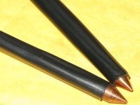
welding tips_7700.JPG

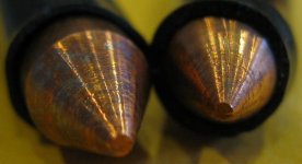
welding tip ends_7696.JPG
 

Attachments

  • welding_all_7703.JPG
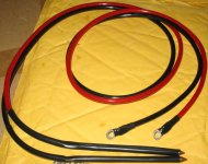
    welding_all_7703.JPG
    107.7 KB · Views: 2,709
Finally got my welder up and running. My objective was to make good welds on tabs for sub-c's. I think it does this job quite nicely.

Here's some pictures with comments:
 
Well Rats! I was gonna put in 4 or 5 pictures with some comments. The "system" grabbed the first one and posted it in one swell foop.

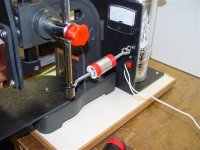
Anyhow, that's what it looks like. You can see one of the Volfenspitzer caps peeking around from the rear of the beast. The cyclops eye on the top is actually an automotive lamp - - filling in as my limiting resistor during charging.

The cubical white box is the SCR - - actually 2 SCR's with only one in use - - recommended by terrarmir.

Electrodes are slightly spring loaded/mounted to equalize pressure.

Afraid I didn't get in under the 100 buck target. More like 250.
 
Another view - - My handy tensioner (the throbmopple with the two red stripes), was a precautionary device. I have a pacemaker and wasn't sure if I could stand up close to the welder when triggered. Turns out I can - - no effects at all.

The power supply is reasonably adjustable - - maybe like 10 to 15 volts - - ergo the voltmeter for reference.
 

Attachments

  • DSC00975.JPG
    DSC00975.JPG
    70.5 KB · Views: 4,304
terramir said:
#3 also try the 1rc charging method and give results on that I found it gives you other values and it's probably somewhere in between. use a battery that is voltage monitored for a power supply, any regulated psu will raise the voltage in order to come closer to the regulated value so it would be useless. need a battery for that a lead acid with at least 10Ah (or two 5Ah in parallel will suffice)
terramir
By 1RC method, do you mean measure the time to charge to .63 (1-1/e) of the final (fixed) voltage? If you do this, I agree you need a very well regulated supply (or batteries). That's why I did the discharge test, since I know the final voltage is 0V ;) For the 1RC test (charging) you could also measure the voltage every 10 sec or so, and plot it, to reduce the measurement errors, since you will have more than 1 measurement to check. You can also make sure the the points lie on a nice straight line on a log-plot. I'll have to see if I can come up with a nice fixed voltage source.[/quote]
well considering @ 10 ohms the current will be limited a big car battery shouldn't have much of a voltage drop. and the thing is I got two "main" caps out of a car capacitor I got different values for discharge and charge namely 1.22F or 1.58F I suspect it's somewhere inbetween.
good luck with your caps BTW 2 volfenhag's should do the trick as far as I was told, but your value seems a bit low there :S

terramir
 
dgcider said:
I have made detailed measurements on a Raptor 1F cap and the Volfenhag 2.0 F cap. The setup was a 100 ohm 1% resistor across the cap, with a digital voltmeter monitoring the voltage. I charged the cap up through a 5 ohm power resistor to the voltage indicated at time 0, disconnected the power supply and starting measuring the voltage every 10 seconds. See graph below. The slope of the straight line on a plot of ln(voltage) vs. time should give the capacitance fairly accurately (at least at that discharge rate). The slope should be -1/(RC), where R is the approx. 100 ohm resistor (measures as 99.7).


I obtained measured capacitance values of .25F per Raptor cap, and 0.60F for the Volfenhag.

-Dan

I had this model of Volfenhag 2.0 F cap on order before you posted this (model ZX-2.2). Received mine today. Measured using the formula C=dt/(R*ln(e1/e2)). Using a 2K resistor I got .55 Farad, using a 50 ohm resistor I got .66 Farad. So, we are in the same ball park.

I noticed that on the package there is a disclaimer on the accuracy of the capacitance. It says the actual capacitance may vary substantially from the stated value. The dealer's ad says the capacitance is 2.0 Farad ±10%. I sent a complaint email to the seller. This qualifies as SNAD=Substantially Not As Described in the paypal agreement.

The seller of the other unit that I bought earlier had me send it back pre-paid and gave me a full refund. I may have to fight this through paypal; we'll see.

Not sure about all the Raptors but most of the ones I see on ebay say that the capacitance is a true 1 farad....

Was yours one of the "true" ones?

Dave
 
There is a nice article in Wikipedia about capacitors and DC circuits. The link is http://en.wikipedia.org/wiki/Capacitor. I am guessing that devices like the Fluke multimeter measure the capacitance of a capacitor by charging an empty capacitor a calculated current for a short period of time, then it measures the voltage buildup across the capacitor. Manipulating the equation, a person finds out that the capacitance can be calculated as follows:
Capacitance = - Charging time in seconds / {resistance in circuit in ohms * Ln ([V0 - voltage across capacitor]/V0)}, whereby Ln is the natural logarithm.

A person wants a fairly large resistance, and a relatively average time period to increase accuracy of measuring units. A car battery or a regulated power supply of about 12-14 volts should be adequate. A resistor in the range of 150-2000 ohm would do, and try and keep measuring time to a minute or less.
Using the above technique, I was able to get 1.8 farads for the Acoustik 6 Farad, PCNC-4.0F, capacitor, and 0.6 farads for the Acoustik 2 Farad, PCNC-1.2F, capacitor. That is roughly 30% of stated capacity. On the other hand, the same formula consistantly estimated the capacitance of Mallory 36,000 uF at about 40,000-46,000 uF.

PS: any current loss in the circuit would overestimate the capacitance of the capacitor, thus why it is important to keep measuring times relatively short.

On another note, I was able to find a reasonably priced Chromium Copper (18200) rods with cheap shipping costs at http://www.nsrw.com/
if anybody is interested in giving them a try!

Abe
 
dbird said:
Not sure about all the Raptors but most of the ones I see on ebay say that the capacitance is a true 1 farad....

Was yours one of the "true" ones?

Dave
The Raptor claims it is a "really 1F, not like the cheap ones" (I measured .25F)

I got it from this ebay listing:
http://cgi.ebay.com/ebaymotors/NEW-TRUE-1-0-FARAD-CAR-AUDIO-CAPACITOR-CAP-RAPTOR-C1F_W0QQcmdZViewItemQQ_trksidZp3286Q2ec0Q2em14QQhashZitem45ed97c110QQitemZ300338888976QQptZCarQ5fAudioQ5fVideo

I wonder how much capacitance the 50F ones really have?

-Dan
 
dgcider said:
<snip>
The Raptor claims it is a "really 1F, not like the cheap ones" (I measured .25F)

I got it from this ebay listing:
http://cgi.ebay.com/ebaymotors/NEW-TRUE-1-0-FARAD-CAR-AUDIO-CAPACITOR-CAP-RAPTOR-C1F_W0QQcmdZViewItemQQ_trksidZp3286Q2ec0Q2em14QQhashZitem45ed97c110QQitemZ300338888976QQptZCarQ5fAudioQ5fVideo

I wonder how much capacitance the 50F ones really have?

-Dan

I have pretty well come to the conclusion that if we/I want actual farads, I'll have to pay quite a bit more than what I initially thought. Fritz has measured close to 3F on a Volfenhag 3F cap, but the 2F units don't even pretend to be accurate. The 3's are getting hard to find; they may not make them any more. Rockford Fosgate's are supposed to be good, as are Tsunami's, but these are both quite expensive. There are other issues too. So called carbon caps (Alumapro for example) are very good for car caps, but their esr is higher than the aluminum (or whatever they are) ones, limiting their discharge current. There are so called hybrid units that parallel low esr, low capacitance components with carbon type high capacitance, higher esr components. My take on those is to stay away from them. The higher esr caps only add welding capacity at the low current long pulse end, not much use from what I have read. I may be wrong here, but that's my take at this point.

Dave
 
fabianix said:
hello to everybody,

many thanks for this topic, it solve to me a lot of problems in order to weld my new lithium cells 8)
I'm going to build my spot welder so I found this cap http://cgi.ebay.it/ws/eBayISAPI.dll?ViewItem&item=220461521192&ssPageName=STRK:MEWAX:IT
and this thyristor http://cgi.ebay.it/ws/eBayISAPI.dll?ViewItem&item=250461962126&ssPageName=STRK:MEWAX:IT
I think the cap should be ok, maybe is real capacity will be 2 or 2.<something> Farad, but regarding thyristor I cannot find his datasheet
I might be wrong, but it seems the same of yours (jeremy's welder, for example)
What do you thing about?

fabianix

I've got the cap and two thyristors (THYRISTOR SILEC IBM 227 A 2395852 3.36 and THYRISTOR SILEC IBM 227 A 2395852 3.02) but I still cannot found the datasheet of thyristors (no match on http://www.datasheetarchive.com/ and similar sites)

anybody knows what are the voltage required for gate activation?
 
fabianix said:
fabianix said:
hello to everybody,
<snip>but regarding thyristor I cannot find his datasheet
fabianix
I've got the cap and two thyristors (THYRISTOR SILEC IBM 227 A 2395852 3.36 and THYRISTOR SILEC IBM 227 A 2395852 3.02) but I still cannot found the datasheet of thyristors (no match on http://www.datasheetarchive.com/ and similar sites)

anybody knows what are the voltage required for gate activation?

I would suggest one of two approaches. Both depend on knowing the average current and voltage rating of your SCRs. Find similar SCRs of the same ratings and package type from either IBM or Silec (whoever that is), and use the datasheet of the similar part. If you can not find similar datasheet from IBM or Silec, then use IR or Powerex or anyone else's product line, again finding similar parts by average current and voltage rating. You won't be too far off that way, at least for the first cut design; then adjust the design depending on how it goes.

Hope this helps.

Dave
 
fabianix said:
fabianix said:
hello to everybody,

many thanks for this topic, it solve to me a lot of problems in order to weld my new lithium cells 8)
I'm going to build my spot welder so I found this cap http://cgi.ebay.it/ws/eBayISAPI.dll?ViewItem&item=220461521192&ssPageName=STRK:MEWAX:IT
and this thyristor http://cgi.ebay.it/ws/eBayISAPI.dll?ViewItem&item=250461962126&ssPageName=STRK:MEWAX:IT
I think the cap should be ok, maybe is real capacity will be 2 or 2.<something> Farad, but regarding thyristor I cannot find his datasheet
I might be wrong, but it seems the same of yours (jeremy's welder, for example)
What do you thing about?

fabianix

I've got the cap and two thyristors (THYRISTOR SILEC IBM 227 A 2395852 3.36 and THYRISTOR SILEC IBM 227 A 2395852 3.02) but I still cannot found the datasheet of thyristors (no match on http://www.datasheetarchive.com/ and similar sites)

anybody knows what are the voltage required for gate activation?

I am using the same IBM THYRISTOR, which I bought off ebay. The gate voltage that I am using to trigger it is about 3 Volts with a 4 ohm resistor connected in series giving a current of about 0.68 Amperes. The setup up works fine, but when I tested this thyristor, I was able to trigger it with 1.5 Volts. However, I have a MILLER THYRISTOR that required more than 1.5 Volts to pass the voltmeter test, and that is why I chose the 3 Volts. I feel it is important to include a resistor in the circuit to limit the current going through the gate.

Abe
 
hello abe,

just tried thyristor..it works. Same behavior, the gate was triggered with AA battery, 1,5V (or also with 18650 li-ion cell, 3,8V 1,5Ah) but the gate remains opened also when I disconnect the battery. Is this correct or wrong? For the test I connected a lead acid battery, 12V 7,2Ah, to the input of thyristor and a car bulb to the out(battery V+ >> thyristor anode >> thyristor cathode >> V+ bulb; battery V- >> V- bulb). Once I triggered the gate the bulb is on also without voltage on the gate. Yours too?
 
that is how a SCR works. once triggered it avalanches and stays on, even if the gate charge is removed. that is why they are difficult to turn off.

the scr will stay on until you remove the lead acid battery. this behaviour is okay for a single pulse welder. the scr will turn off once the big capacitor is drained low enough.

rick
 
If anybody is interested in Cheap Nickel Strips, there is somebody offering it on ebay for less than $20.00 a pound but you have buy about 30+ pounds. That is a very good price if you tried to shop around for it. The link is:
http://cgi.ebay.com/ws/eBayISAPI.dll?ViewItem&item=290350714899&ssPageName=STRK:MEWAX:IT
The only bad thing is the thickness is about .0175", but it is not a big problem if you want to get a Rolling Mill which sells on ebay for about $200.00. The link to it is:
http://cgi.ebay.com/ws/eBayISAPI.dll?ViewItem&item=360183627037&ssPageName=STRK:MEWNX:IT
Getting the same quantity of Nickel strips from Admiral Steel would cost about $1,800.00 compared to less than $800.00 for this deal. Other places that sell Nickel strips in quantity include http://www.componentconcepts.com/, which sells a pound for about $40+.

Abe
 
Here is my links for battery nickel strips:

http://mtobattery.com/store/page7.html
http://sunstoneengineering.com/site/pages/sales
http://www.sunstonespotwelders.com/spot-welding-accessories-nickel-strips.php
http://www.hartsbatteries.com/battery-weldsolder-tabs-c-40.html
http://www.onlybatterypacks.com/items.asp?db=29
http://www.powerstream.com/spot-welder.htm
 
This is the cheapest Nickel that I could find http://www.admiralsteel.com/shop/201.html
 
Hi! An excellent topic you have here.. :)

I'm thinking to build a CD welder too, with these MOSFETs:

IRLS3036-7PPbF
http://www.irf.com/product-info/datasheets/data/irls3036-7ppbf.pdf

I just can't figure out how many of those I will need.. :?

I was thinking to use something like 0.5F & 48V, so max. ~600Ws. Is there any drawbacks if I use this high voltage or is the energy the most important thing? Sunstone uses max. 25V in their 750Ws welder. I think I will be using max. 36V with my current power supply, but I think it's wise to have enough fets for 48V. 48V shouldn't be too much to get electric shock, with dry hands at least. :mrgreen:

If you count ESR of capacitors (many parallel: ~0.65mΩ), resistance of MOSFETs (if 10 parallel is enough: ~0.15mΩ) and nickel-nickel contact (~3mΩ?, how about copper?) you get 48V/3,8mΩ = ~12600A. It's quite a lot... :roll:

So if I use thick and short wires etc. I might get >7000A peak current? How many of those fets do I need? Datasheet says 1000A peak current, but it's continuous pulsing at 10V (Repetitive rating; pulse width limited by max. junction temperature.). At 48V those can handle only ~1A 10ms? I can't figure out single pulse current for these..

Is there anything special that I will need if you compare to SCR circuit? Varistors (or TVS) to handle induction peaks (like nemo did) at turn off and (parallel?) fet drivers to get high enough rise times? I was thinking to use an AVR microcontroller to control the welder.. Main reason to use mosfets is that I get very low resistance switch that I can use for other projects too. Thanks for any help! 8)
 
Hi Ekke,

I am not familiar with MOFSETS, but the copper wiring resistance is usually about 2mΩ, the following link will take you to a site that would discuss it:
http://www.powerstream.com/Wire_Size.htm

Also, SCR's do not have a high resistance. It is usually on the order of 1mΩ. I would say that it is reasonable to estimate the nickel tab resistance at about 3mΩ. The issue at hand is the ESR of the capacitors. If you use many computer grade capacitors, you might get a low ESR, and high currents. One way to measure it would be to use a Clamp on Multimeter like the Fluke 337a, or even the Fluke 355. A cheaper alternative would be to buy the following Clamp on Multimeter (Fluke LEM LH1040 - discontinued model), which has the advantage of being able to be hooked to an oscilloscope:
http://cgi.ebay.com/Fluke-LEM-Clamp...emQQptZLH_DefaultDomain_0?hash=item4ceba0c651

You can do repeated measurements at low voltage in order not to exceed the maximum range of the Clamp on Multimeter which is about 1000 Amps. It would be interesting to find out the maximum current you get as opposed to the maximum calculated.

I am using a Power Acoustik 6 Farad car audio capacitor at about 12~15 Volts; and the maximum current I got with this setup was about 200 Amps. However, I am still getting great tab welds with it.

PS: The measured Acoustik capacitor capacitance is about 1.8 Farads, and not 6 Farads. So my maximum power output is close to 200Ws.

Abe
 
Abe said:
Hi Ekke,

<snip>

Also, SCR's do not have a high resistance. It is usually on the order of 1mΩ. I would say that it is reasonable estimate nickel tab resistance at about 3mΩ. The issue at hand is the ESR of the capacitors. If you use many computer grade capacitors, you might get a low ESR, and high currents. One way to measure it would be to use a Clamp on Multimeter like the Fluke 337a, or even the Fluke 355. A cheaper alternative would be to buy the following Clamp on Multimeter:
http://cgi.ebay.com/Fluke-LEM-Clamp...emQQptZLH_DefaultDomain_0?hash=item4ceba0c651
<snip>
I am using a Power Acoustik 6 Farad car audio capacitor at about 12~15 Volts, and the maximum current I got with this setup was about 200 Amps. However, I am still getting great tab welds.

PS: The measured Acoustik capacitor is about 1.8 Farads, and not 6 Farads. So my maximum power output is close to 200Ws.

Abe

Hi Guys:

I'm not sure this amp-meter is good for one-shot transients. And an RMS reading is not what you want for the current measurement. You want the peak value and the time constant. Given that you have a good measurement on the capacitance, measuring the RC time const will give you the total discharge effective R.

Dave
 
Hi Dave,

You are right about the RMS current reading. It is averaged over 100 ms, and it is not reflective of the peak current reading. However, the Fluke LEM LH1040 has the ability to be hooked to an Oscilloscope, and by turning a switch in the battery compartment can give instantaneous vs. RMS readings according to the manufacture. I am sorry, but I do not have an Oscilloscope, and therefore, I cannot do the maximum instantaneous current reading.

However, the maximum Crest Factor for a true RMS measurement is 6, if I am understanding the manufacture's literature right. Therefore, the maximum error cannot be more than 6 times the RMS reading. Hopefully, it is less for a logarithmic decay discharge curve. Whenever, I get an Oscilloscope, I will revise the above value. The following link gives more information about the Clamp on Multimeter:
http://www.bis.fm/assets/documents/faxdatasheets/Lem Heme LH240 LH1040 LH2040 Data Sheet.pdf

Abe
 
Update - comments - questions. I've made several hundred welds with my simple device (pictures on page 26). All of them on sub C and 4/5 sub C nicads. We are using both the .250 and .375 width nickel stock - - .005 in thickness. Have the voltage up to almost 15 volts now, and seem to be getting consistently good welds.

I've learned that the electrode pressure is very critical. With my arbor press platform, it is easy to get too much pressure - - This results in dimpling the tab material as well as the cell. In turn, the contact area is greatly increased, and the temperatures achieved don't result in as good of a weld as you get with lower electrode pressure.

Too LITTLE pressure can result in a blowout - - big holes in the tab material and no weld at all. If I make the electode ends too sharp, they don't hold up nearly as well.

I'm finding that some of the better quality tools have battery packs using thicker tab stock. .010 is popular. Other than trying welds with scraps, I haven't really studied the use of thicker stuff yet. I THINK I can make good welds with .010 tho, and may order some to do a better study.

My present power supply is limited to about one amp or so. As a consequence, the charging time is pretty long between welds - - maybe 10 seconds or so. It is easily monitored by watching the lamp I am using for a limiting resistor.

A question for the Gurus in our midst: I know that a heavier current supply will reduce charging times, but am wondering if that may come at the expense of capictor life?? Some informed response on that would be appreciated.

oldusedbear
 
Back
Top