build your very own Lebowski controller !

I'm not going to pretend I know anything about electronics, but...everyone that I am impressed with [that has experience] is excited about this. I was already VERY impressed with your axial-flux DIY motor (which I understand enough to be blown away by it).

You are doing the E-bike world a great service by publishing this motor and controller...
 
only two more features to be the best on earth and match military grade sensorless

sensorless coil temp reading (easy to implement)

sensorless magnet temp estimation (hint magnets weaken with temp)

use the Force Lebowski

:)
 
Thank you Sir Lebowski for sharing this great technology with us all. Looking forward to building /buying one for the ultimate wheel motor concept now in planning. Hoping to run it sensorless. Would be great if someone will make extra circuit boards and accumulate a reasonable priced parts kit for it or better yet sell finished units if time runs too short.
 
In the mean time I got it finished and man it runs good :D (see the added teaser picture to the first post)
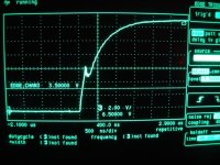
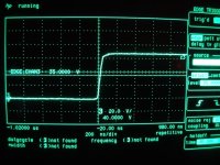
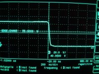
some signals measured in the output stage:

gate signals, rising and falling:
DSC01475.jpg
View attachment 2

output signals to the motor:
DSC01476.jpg
DSC01477.jpg

blipping the throttle (you can hear motor running in the background):
[youtube]Pue2eASs8K8[/youtube]
My power supply does not like power being put back into it, a tiny amount of regen when the throttle is released causes the normally 65 V to rise to around 100V
 
Lebowski said:
In the mean time I got it finished and man it runs good :D (see the added teaser picture to the first post)
some signals measured in the output stage:

gate signals, rising and falling:
View attachment 3
View attachment 2

output signals to the motor:
View attachment 1


blipping the throttle (you can hear motor running in the background):
[youtube]Pue2eASs8K8[/youtube]
My power supply does not like power being put back into it, a tiny amount of regen when the throttle is released causes the normally 65 V to rise to around 100V
The second picture worries me what amperage/voltage is this at?
 
Lebowski said:
The second picture shows the low side gate when the FET switches off. After 400ns of deadtime you can see a small 2V glitch when the high side switches on.
Yes what voltage is this at and amperage?
 
Arlo1 said:
Lebowski said:
The second picture shows the low side gate when the FET switches off. After 400ns of deadtime you can see a small 2V glitch when the high side switches on.
Yes what voltage is this at and amperage?
65V and no amps, it was done with the PWM test function to check for ringing in the gate circuit (due to inductance). Same for tbe output signals, no load PWM test, showing there's negligible ringing. No need for snubber as the internal inductances are low. The video shows the signals under load, but i don't know how many phase amps. But you have to admit, they're the cleanest looking signals ever posted on this forum :D The real test will be on the street.... as i have no workshop with a dynamometer...
 
Depending on the type of ringing, some only manifest when the fet is switching under current.

You're right though, with your inductance super low, the only ringing you could have would be extremely high frequency stuff AFAIK.
 
I find even when I get everything looking good with pwm test mode it usaly goes to shit under a true load. Also that miller effect will grow as voltage increases.
 
So I have a question for all you controller aficionados. With all the work Lebowski has done to make his superior controller
duplicatable by others, could someone that is good at following directions build one of these controllers without understanding
what is actually going on?
 
That is kind of the intention of this thread. If you have the feeling that you can do all the building steps shown above
you're halfway there. The second thing that is necessary is that you can open the KiCad database, see the board
with the component values and placement, and that you can open the schematic files to see the explanatory text...
 
No problem for me to do the lead bending /soldering and follow the parts placement pics to put one together. What scares me off at least now that I am playing catch up with work most days, is the board building and sourcing / inspecting most every component. Don't have enough of a clear headed time block to think it through. Wish I could just order a kit or have the luxury of ordering a finished unit.
 
speedmd said:
No problem for me to do the lead bending /soldering and follow the parts placement pics to put one together. What scares me off at least now that I am playing catch up with work most days, is the board building and sourcing / inspecting most every component. Don't have enough of a clear headed time block to think it through. Wish I could just order a kit or have the luxury of ordering a finished unit.

+1.

However, this controller would be worth the hassles of making your own board. This is like next-generation BLAC control.
 
I would love to have Lebowski's board as a reference for my own build, so I'm considering to get a PCB made from the gerber files and get an order from Digikey. I see no problem in ordering e.g. 5 PCB's and x5 components to build either 4 kits or 4 complete boards + one for myself. So if people really want finished boards, I'm willing to help out.
 
I would also like 2 controller kits, Which I could complete (with no previous electronic assembly experience) although I have built my own house... Does that count? If a group wanted to get together and do a joint build session I could host an hour south of Seattle, wa.
 
Hi Lebowski,

How do we go about getting a brain from you for this board? My brother (Bluefang) has asked me to build him 4 of them for his 2 hubmonstor motors from John in CR. I've sent the Gerbers off for quote so should get the boards in a couple of weeks and order parts from Digikey per your kicad schematics.

He also wants to run high current and high voltage so might need to change the current sensors as that line only goes to 200 Amps how do you set the scaling of the current sensor output to your brain?

With the hubmonstor motors they are 6 phase but my brother and John both seem to thing just drive each set of 3 phases with a master controller and it will be fine. I saw your post about running master slave with the slave offset from the masters timing by 30deg which sounds right to me. Can you expand on the issue of driving it with two master boards per motor?

I'm new to the electric BLDC motor scene so some of these voltages and currents seem a little nuts to me :p

Cheers

Chris
 
purple_jeep said:
Hi Lebowski,

How do we go about getting a brain from you for this board? My brother (Bluefang) has asked me to build him 4 of them for his 2 hubmonstor motors from John in CR. I've sent the Gerbers off for quote so should get the boards in a couple of weeks and order parts from Digikey per your kicad schematics.

He also wants to run high current and high voltage so might need to change the current sensors as that line only goes to 200 Amps how do you set the scaling of the current sensor output to your brain?

With the hubmonstor motors they are 6 phase but my brother and John both seem to thing just drive each set of 3 phases with a master controller and it will be fine. I saw your post about running master slave with the slave offset from the masters timing by 30deg which sounds right to me. Can you expand on the issue of driving it with two master boards per motor?

I'm new to the electric BLDC motor scene so some of these voltages and currents seem a little nuts to me :p

Cheers

Chris

To get a controller IC you can send me a PM. I ask for 20 chf (swiss franc) for a v1.xx (the ones with hall sensor startup
or push-start) and 25 chf for v2.xx (the version with the HF tone). In combination with a controller IC I can add a 12F617 for
the power supply for 5 chf. I can fit upto 6 chips into one envelope, which adds 5 chf for shipping. I have a paypal so that's
easy. All in all the controller IC for one controller costs about the same as 6 FETs, which I think is reasonable. If you have
a Pickit programmer you can source your own 12F617 and program it with the hex file provided in the second post of this thread.

The current sensors on the board run on 5V, and give 2.5V out for 0A and then higher or lower voltages dependent on
the current polarity (sensor must be bi-directional). I know Arlo uses wire feedthrough type current sensors which run on 10V, and give 5V out for
0A. In such a case you just need a resistor devider to half the current sensors output voltage to 2.5V. Just make 100% sure the
polarity / current direction is OK ! When the current flows from controller to motor the sensors output voltage must
be higher than 2.5V, and lower than 2.5V when the current flows from motor to controller.

Well, with 2 master controllers, I don't really know what will happen. This is what I have warned John about, it's a risk.
It will I think depend on how the motor is wound. Next to the fact that it is a motor, it is actually also a giant transformer
with 6 windings. If the motor is wound such that the magnetic fields of each phase are closed within themselves I think it
will be OK (because the transformer effect will be negligible). If however the motor is wound such that the return path of
the magnetic field goes through other windings, then the controllers will 'see' each other which I'm afraid (but not sure) will
mess everything up.

I know what you mean about voltages and currents... at work I'm designing an ADC for use in a microcontroller chip, 1.8V supply
and less than 2mA current consumption !
 
Hi Lebowski,

Great! I will confirm with Derek (bluefang) which version he wants and get them on order from you! I will likely get the 12F617 from you also as it saves me from digging up the programmer at work and working out how to use it :).

Ok i can set up an appropriate divider so 0 is max amps reverse and 5 is max amps forward but you don't care what the actual value is (5v = 100Amps or 5v=300Amps) right?

Any thoughts on using IGBT's instead of Fets? I noticed the driver chip your using also says it will drive IGBT's (have not read into it much yet) with the voltage and current Derek wants to run IGBT's make the most sense either standard dual package or an IPM version.

Guess he will try two masters and we will see what happens unfortunatly I will be building the electronics here in the USA and sending them to him in Aus to fit to his motor and batteries so cant do much testing.

Cheers

Chris
 
Version 2 :mrgreen: I want to ditch the hall sensors and use the best lebowski has. If i am going to do this project i might aswell do it properly as Leboski and Arlo already have proved the brain works. Great to see you still use the purple jeep name, pretty easy notice even before reading the posts.

The motors are wound on seperate teeth and can be run perfectly well by sensorless and sensored controllers so i don't see them having a problem and thats a risk i am willing to take. Worst case i have 4 of the best controllers around to use on 4 seperate motors in 4 seperate bikes rather then just 1 bike and a ton of power. Thanks for helping out brother. :mrgreen:

If you can use standard IGBTs that would be awesome as there is alot more choice, but i guess thats up to the drivers.
 
Back
Top