Danny Mayes
1 kW
+1
Me too
Me too
EKOBA said:Hi ,
Where can I find some chips btw I am a UAV guy but still would like to try out...If some one can direct me to a complete board..
Regards
http://www.vimeo.com/xerofly
purple_jeep said:Hi Lebowski,
I am back at working on the IGBT version for my brother, I need a 24V supply for the drivers so what do you think of the following:
- From what I can tell from your PIC12F617 code you are comparing the signals from the 5V and 15V lines via external resistive dividers to 0.6V internally (my assembly is bad but your comments are good)
- If I modify the divider network for the "15V" line to make it 0.6V from 24V and then add a 7815 3 pin reg from the modified 24V to make the supply for U12 do you think this would be ok?
Cheers
Chris
There's not really anything to change when moving to lower voltages. Of course you can use lower voltage caps and FETs (which may need a change in gate resistance based on different gate charge)CoulombMotorsport said:Hi Lebowski,
Majorly impressed by your controller! Only wish I'd known about it a few months ago when I was in Switzerland (I'm live in Perth, Western Australia). Just wondering what components I would have to change in order for your controller to work at 30V min, 55V max as I see you are using it around 80V?
Additionally, do you have an efficiency figure for the controller? I plan on building one for use on my Electric efficiency vehicle and so am chasing efficiency gains wherever possible.
Look forward to hearing from you.
James
Lebowski said:There's not really anything to change when moving to lower voltages. Of course you can use lower voltage caps and FETs (which may need a change in gate resistance based on different gate charge)
but other than that it should be OK.
I do not know the efficiency of the controller, I do not have a motor stand to measure that....
Depends on the output stage... you need 5V minimum for the chip and the current sensors. FETs like to be driven with a 15V gate signals... Maybe there are FETs out there for which 5V would be enough, but I can imagine you still need a high current gate driver. Don't know if there are 5V drivers like that available.Danny Mayes said:Lebowski said:There's not really anything to change when moving to lower voltages. Of course you can use lower voltage caps and FETs (which may need a change in gate resistance based on different gate charge)
but other than that it should be OK.
I do not know the efficiency of the controller, I do not have a motor stand to measure that....
Hey Lebowski, just because we are on the subject, how low a voltage could you go? Could you run it on a single cell? This is not my strong area at all but I assume the chip would need at least 5volts so maybe 2 cell would be the minimum?
D
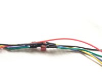
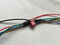
Didn't you have this in you sch at first then remove it over time? :lol:Lebowski said:Starting with v2.60 the controller IC uses the hall signals directly. From Izeman's MAC I have seen the hall sensors or their wiring pick up a lot of noise as the phase current increases, to the point where the hall sensor signals become complete garbage. Therefore I recommend to add the following analog filter in each hall signal:
As all analog filters have a delay, with the above components the delay is 10 degrees at 5 k-erpm.
In 2.60: the calibration speed is half the max speed set with options a and b in the erpm menu. Best to set these to around 10k-erpm, as not to have too big an error in the hall measurement due to the analog delay.
For existing PCB's: the capacitors can also be to 5V, so on the board you can replace the resistors to 5V with capacitors. The resistors can then be added in the hall wiring.
I was only following your advice.Lebowski said:ehmyes.
m) temperature sensors
n) miscellaneous
y) chip status at last drive_1
z) store parameters in ROM for motor use Last entry into drive_1:
error bits: over_i_total or over_i_error
drive LEDS: ..23
time spent: 0.348 sec
throttle: 7 %
wanted_i_torque: 3.8 A
wanted_i_fieldweak: 0.0 A
filter_i_torque: 13.1 A
filter_i_fieldweak: 2.0 A
filter_i_error, dr3: 0.7 A
filter_i_total, dr2, dr23: 14.2 A
filter_i_error, dr2, dr23: 0.7 A
Vout_real: 21 %
Vout_imag: 3 %
Vout_scaling: 0
speed_sensorless: 3.69 k-erpm
filter_speed: 11.75 k-erpm
accelleration: -46 % phase control loop, drive 3
b) 1st order: 480
c) 2nd order: 24.0000
d) 3rd order: 0.6000 Last but 1 entry into drive_1:
error bits: over_i_total or over_i_error
drive LEDS: ..2.
time spent: 0.006 sec
throttle: 6 %
wanted_i_torque: 3.1 A
wanted_i_fieldweak: 0.0 A
filter_i_torque: 19.8 A
filter_i_fieldweak: 0.0 A
filter_i_error, dr3: -0.4 A
filter_i_total, dr2, dr23: 13.1 A
filter_i_error, dr2, dr23: -0.4 A
Vout_real: 13 %
Vout_imag: 0 %
Vout_scaling: 0
speed_sensorless: 0.00 k-erpm
filter_speed: 0.00 k-erpm
accelleration: 0 % amplitude control loop
h) 1st order: 240
i) 2nd order: 12.0000Lebowski said:As all analog filters have a delay, with the above components the delay is 10 degrees at 5 k-erpm.
For existing PCB's: the capacitors can also be to 5V, so on the board you can replace the resistors to 5V with capacitors. The resistors can then be added in the hall wiring.


yes. but try to source smaller capsArlo1 said:Good idea I think I will need to do the same!
I have a great selectionizeman said:yes. but try to source smaller capsArlo1 said:Good idea I think I will need to do the same!
you tell me NOW!!Lebowski said:I'm starting to wonder again about the effectiveness of this... am very curious about whether you guys notice the difference or not. I did measurements this afternoon and have the sneaky feeling the digital filtering I put inside the chip is more effective than the analog external.... for the same filtering bandwidth (read: phase shift penalty) I see better results with the digital filter. So please let me know your experiences !
It probably has the pull up resistors inside.... you either have the circuit from a few posts ago, or the pull up resistors,but not both...izeman said:connected the circuit to my kelly controller and it refused to work. it just gave "hall error".
