Building a motor

SDM Magnetics. Lucas

sales10@magnet-sdm.com

My mistake n was getting n48sh magnets. high temp ability magnets and 230c magnet wire: the power output and durability is better than in any motor available.
 
Hi

mxlemming said:
I just ordered the ant innovation 12070.

Please please, when you get it, post some details about the 12070. Make a thread!
I've seen very similar "12070" motors also offered by freerchobby and a few alibaba vendors.
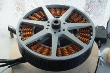
The form factor is imho excellent for ebike use!
But the specs from various vendors are all over the place. some quote 3.5A no-load current at 24V, some 7A at 15V,
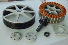
Also, would be interesting to know how the stator is connected to the aluminium "base". Is it on aluminium "spokes" or on a cylinder?
(cylinder would be awesome because then it's "heatsinked" to it, and bolting the motor to an Al plate would further improve cooling)

Back to on topic, as you've briefly touched on LRK and dLRK, that's the only thing I can contribute (just so my post isn't completely off topic)

I've recently read 2 threads about dLRK vs LRK on rcgroups.com forum, some posts coming from Christian Lucas (the L in LRK).
I hope I can summarize the differences of dLRK over LRK well, but go read the posts from the man himself. (for the record, he did not invent the winding, just made it popular, but he understands motors really well. like REALLY well. He also tells the story. The threads are definitely worth a read!)

-> dLRK would have shorter coil ends (the useless part) for the same number of turns as LRK. This is especially significant for short motors, where the ends make up a higher percentage of the total wire length. If the motor is long, this is negligible
-> dLRK would have a "nicer" back EMF shape, from an ESC point of view compared to an equivalent LRK. Meaning modern ESCs have an easier time controlling a dLRK than a LRK wound motor.
-> LRK would have a little lower kV for the same number of turns than dLRK

Also, my 2 cents: a LRK wound stator, with its bulkier coil ends, will result in a tiny bit bulkier motor, all else being equal. If you're just rewinding, you might have difficulties to fit the rewound stator in the can :)

Regards,
 
Those 12070 motors are pretty good I reckon, optimised for high continuous torque.
Folks here didn't like them much years back cos of high idle current, much low inductance counselling was needed..
I have heaps of data on them, and was running 32khz pwm to sort things out, for now here's a vid of what a 30mm stator 2.4kg version can do.

https://youtu.be/qfJT0Ww3tdc
 
toolman2 said:
Those 12070 motors are pretty good I reckon, optimised for high continuous torque.
Folks here didn't like them much years back cos of high idle current, much low inductance counselling was needed..
I have heaps of data on them, and was running 32khz pwm to sort things out, for now here's a vid of what a 30mm stator 2.4kg version can do.

https://youtu.be/qfJT0Ww3tdc

That's quite pleasing. Watched a few of your videos.

The one I've ordered has a 40mm stator height. Hopefully even more power :twisted:

I'll be running 35khz center aligned pwm. Do you recall the kV and inductance of your one? What controller did you use and how much power could you feed it? (Current at what kV and speed)?
 
The ant motor is ridiculously low inductance. 7.5uH and less than 10mohm resistance. This is going to be a mission to drive even at 35kHz pwm. It spins though... Moved to another thread.

In other news, the slow boat from China arrived with the stator. It weighs only 450g. With the copper (about 200g) and the magnets (300g ish) and the 3d print plastic it should be about 1.2kg which is very light compared to the ant - no more than the 8080 motors. Should have much more torque but... Who knows about power, heat, max rpm.

IMG_20211012_102136022.jpg

IMG_20211012_102523715.jpg
0.2mm laminations :D

IMG_20211012_105805831_HDR.jpg
Went for 0.7mm wire in the end. Actually measures 0.77mm,i guess they meant the copper diameter. It'll take about 12A continuous without becoming too hot to touch when i plugged it into my power supply. 15A is about the limit when blowing gently on it. I'll try to get 6 or 8 strands in to enable 100A but obviously the kV will need to be got down to 60ish.

Unfortunately, this motor is ending up somewhat optimized for availability rather than optimized for excellence. The halbach array is on hold because those magnets turned up axially magnetized which wasn't very useful.
 
youre going to use a 3d printed hub in the center? Maybe im misunderstanding what you wrote.

i got the 84100 stator and getting this part made from aluminum as the hub. i shrunk it down to the minimum height i think possible and added huge bearings. if anyone has any advice i still have a bit of time to alter.

it was like 90$ for this custom aluminum hub but if Id gotten 10 it would be like 16$. Ant said they'd sell this 84100 stator for 55$ each.
 

Attachments

  • Capture.PNG
    Capture.PNG
    15.6 KB · Views: 504
Hummina Shadeeba said:
youre going to use a 3d printed hub in the center? Maybe im misunderstanding what you wrote.

i got the 84100 stator and getting this part made from aluminum as the hub. i shrunk it down to the minimum height i think possible and added huge bearings. if anyone has any advice i still have a bit of time to alter.

it was like 90$ for this custom aluminum hub but if Id gotten 10 it would be like 16$. Ant said they'd sell this 84100 stator for 55$ each.

3d print for now. Once I've got it spinning I'll machine one. I'm also going to be using a3d print rotor.
 
Be careful with 3d printed rotor, if it is from plastic might not be strong enough and deform from magnets force (all those magnests pulling the iron core add up), or worst if spinning to fast might fly apart at those diameter you have there.
I suggest you use thinner copper wire strands somting like 0.35 mm but no higher thand 0.5mm, that way you get better fill, skin effect, and it will be way easier to hand wind with thinner strands, thrust me i know this becouse i compleatly built a 20Kw out runner 216mm diameter. This motor rotor had a 320kgf toward iron stator core, and needed a special tool to pull and put the rotor over the stator, hence the wornings about plastic 3d printed rotor. When you machine the parts from metal, do consider thermal expension for the bearings places, a 40mm hole in aluminum block at 80 deg C can grow up to 0.015mm, that can mean difference between loose to sliding or sliding to tight feeting, that heat transfers from iron core to center bearing hub very easily.
Oather than that i wish you have greate success.
 
i find winding thicker wire easier and get better fill. tie it to a doorknob and the other end wrap it on and you can pull it tight...so tight as to stretch the wire, and then you can have a nice organized coil with minimal gaps.

but what erpm will skin effect occur and maybe thats a good reason to keep it thinner?
 
The skineffect is influenced by base PWM also, not just the erpm (motor frequency), atleast if motor si not running at WOT, the winding will se that PWM frequency, hence high pitch sound from motor when base PWM is under 14khz (depending on motor and human ears). 0,51mm copper can go up to about 68khz for skin depth 100%, if i remember correctly. As for better fill, how do 4 big circles fill a square vs 16 smaller circles the same square, draw it and see.
 
My understanding is that the pwm frequency is only relevant up to the magnitude of the role current it induces i.e. 35kHzpwm might induce 0.xmm skin but the role current is only a few amps so it's not that important. The DC or low frequency erpm component is calculated separately.

Mihai, your motor looks really really nice BTW.

3d printing is for prototyping. Once running well I'll swap to metal.

I tested a 3d print disc to 10krpm the other day, so I think I'll be ok at about 3krpm with the magnets. That's 10x the acceleration.

Main goal with this is learning not self propulsion, I'm going to rewind in star, Delta, maybe another pattern, lrk, dlrk... Thicker wires are just more practical for now.
 
Mihai_F said:
As for better fill, how do 4 big circles fill a square vs 16 smaller circles the same square, draw it and see.
sure smaller wires will fit better if it's only 16 turns of wire and that's easy to organize but keep adding more and thinner wires and it ends up a twisted mess where they dont fit into each other well and ends up less copper in my experience.
but he's doing everything maybe and will see.
 
Here is how : https://www.avrfreaks.net/forum/electric-propulsion-system-ppg-and-ultralights, that motor (20kw) has 60x0,5 strands tristed so they stay nice, and was decent to work with.
 
Mihai_F said:
Here is how : https://www.avrfreaks.net/forum/electric-propulsion-system-ppg-and-ultralights, that motor (20kw) has 60x0,5 strands tristed so they stay nice, and was decent to work with.

Is that a cad render or an actual photo?

What's the weight, kv, inductance, resistance...?

Where did you get the stator from?
 
Yep the real thing, 7.7kg, 10uH, 6mohm per phase, 36kv, N45 40x10x5 magnets, stator laminations are laser custom cut.
 

Attachments

  • DSCF7233.jpg
    DSCF7233.jpg
    211 KB · Views: 445
  • DSCF3498.JPG
    DSCF3498.JPG
    324.6 KB · Views: 445
Mihai_F said:
Yep the real thing, 7.7kg, 10uH, 6mohm per phase, 36kv, N45 40x10x5 magnets, stator laminations are laser custom cut.

That is a very beautiful motor. No two ways about it.

Where did you get the laminations cut? And how much? I got done quotes but it was crazy money so I'm making do with ones I can buy.

I'm not planning on especially optimizing this one. Education only. If i get it propelling my ebike I'm happy enough.
 
I got them cut in italy, i have to search for that complany, and it was 600 euro (in 2016) fo 2 sets preaty pricy, but for 10 sets they asked for 1000 euro... It ain't cheap, but considerind that here in europe there is a company that sells this kind of motors (bldc outrunnets) and they asked 1500euro for a motor, and i got mine done for half of that is not that bad after all.... And i flew electric powered 😁, witch is even greater 😁
10x for appreciation of the motor 😄.
 
Mihai_F said:
I got them cut in italy, i have to search for that complany, and it was 600 euro (in 2016) fo 2 sets preaty pricy, but for 10 sets they asked for 1000 euro... It ain't cheap, but considerind that here in europe there is a company that sells this kind of motors (bldc outrunnets) and they asked 1500euro for a motor, and i got mine done for half of that is not that bad after all.... And i flew electric powered 😁, witch is even greater 😁
10x for appreciation of the motor 😄.

0.2mm laminations ? I presume you fot 10 of them?

What's the diameter?

How many poles; I count 30 slots but struggling to count the poles. 32 or 40 seem like the only options.
 
Unfortunately 0.5mm laminations, i coukd not find 0.2mm sadly, so i have 700w loss in heating the iron, the stack is 40 mm hight, hence 40x10x5 magnets, so 80 pieces per set, i only got money for 2 sets at that time, stator is 192mm diam 30 slots and 40 magnets, ABC winding scheme trapezoidal BEMF, 3 halls, and temp sensor. The neat thing is that i made my constroller sensored but i can advance the timing in software by 30 electrical degress in each way, and that is useful for getting the wright efficiency, plus it helps big time fine matching the motor to propeller.
 
Have you read anything on the steel grain structure of the laminations?
I just remember hearing it from Justin but I needed to confirm if such a thing is real to not look bad.
https://en.wikipedia.org/wiki/Electrical_steel
Grain orientation
Electrical steel made without special processing to control crystal orientation, non-oriented steel, usually has a silicon level of 2 to 3.5% and has similar magnetic properties in all directions, i.e., it is isotropic. Cold-rolled non-grain-oriented steel is often abbreviated to CRNGO.
 
Yes, the lamination supplyer said that is non orientated grain, witch is a must for motors, the material is m330-50a
 
Could u use orientated grain electrical steel with a segmented stator? I get that the oriented steel is best for magnetization in a certain direction ..but if the segments were all created with the oriented steel magnetizable in the desired direction? Sounds possibly ideal.

Very nice looking winding.
 
I might work saounds doable, i head some people over the internet somewere trying it, but it might be a mechanical challenge trying to fix the segments in to place, they have to be really sturdy, all the motor torque acts on them...
 
I think this sounds like a really good idea. Fixing it should be easy enough, just give them a small interlocking feature and then clamp them with the hub. Could pin them to the hub if necessary with a non metallic pin.
 
Back
Top