Building a motor

Maybe he wound it imbalanced and the resistance he feels in his hands turning is the result of the voltage between phases producing a magnetic force, and that’s the main drawback to delta: it needs to have all phases equal inductance.

It’s hard to get them exactly balanced even with the same amount of turns.
 
larsb said:
mxlemming said:
Delta feels much stiffer to spin by hand, and for a speed that has the same "key" (sound, audible frequency) takes over 2x as much power in delta as star. You can see on the 'scope, the motor really does not freewheel as well, the speed drops much more rapidly.

I think this is enough evidence for what I was looking for in star vs delta; star is better. Much better. I should try to reconfigure my massive

I haven’t seen a any real evidence that star gives a large benefit over delta, it concerns me a bit when you make this comparison without numbers - are you really comparing DC power at the same rpm? What are the numbers?

DC input from the PSU at same rpm. (Edit... At the same voltage!)

0.5A for star, about 2A for delta.

I can feel the difference just turning it by hand.

This motor is not a good motor (yet) the air gap is 3x as big one side of the rotor as it is the other.

The coils are not wound imbalanced like hummina suggests, but the out of balance magnetic field will be substantial.

I've suspected for a while that perfectly built motors are equivalent in star and delta (the inductance and resistance will mask small errors) but in imperfect motors, of which mine is a very very imperfect example, the Delta configuration effectively shorts those errors where the star lets them see an open circuit.
 
My motor was run in both ways wye and delta, in delta 36kv 7A no load at 37v, in wye 21kv 4.1A no load at 37v.
Care must be taken when making the delta connection, so that all coils pull/push in the same direction.
Now about drive pattern, delta motors can be driven in push or pull mode (pull or push the magnets) , wye motors have 2 coils that are energized one puls one pushes, but delta has only one coil energized witch can pull or push, and that gives diferent results depending on motor. Another important thing in sensored mode delta and wye drive patterns are different, furthermore in wye, in order to reverse rotation 2 phases can be swapped, or switch polarity of the driven coil in the drive pattern (software), but in delta it does NOT work the same way, in order to reverse rotation all 3 phases must be swapped in a certain way, or a certain different coil must be energized in sw. So the delta motor can be runn in 4 ways, 1 push and 1pull in CW rotation and 1push and 1 pull in CCW rotation. Thrust me, i know this, because i bashed my head a few months experimenting and drawing conclusions, all information out there on the "interweb" is about wye motors they are much more simple to drive, no one talks about delta drive pattern.
All upward of 15Kw motors for aero use that i have seen are delta terminated, and this is because fewer turns are needed to achive same Kv, and winding has smaller resistence (lower losses).
Now about the BEMF waveform, depending on winding scheme and pole pairs it can be trapezoidal or sinusoidal, and if i remember correctly delta or wye termination also affects that, but i have to check that.
Edit here, typo:
Sensorless controllers have a tough time controlling delta motors, i tried on my motor, on wye was walk in the park for a sensorless ESC, but in delta it was hard to start and sometimes would lose sinchronisation.
 
Could be distributed?

In any case, this should have it's own thread rather than being posted on everyone else's.
 
usertogo said:
Hummina Shadeeba said:
Those magnets look awfully wide in relation to the stator teeth, no? Or are pairs of teeth wound to be the same polarity?
Its all parametric, don'T remember might have figured wrong - all 3 phases up and down within each magnet cycle?

mxlemming said:
Could be distributed?

In any case, this should have it's own thread rather than being posted on everyone else's.
You think somebody would like to work on this?
Im game, just what would it be _3d printed motor experiments discussion_ ?

I doubt anyone else will have much interest in working on it, but they would be very interested in seeing the results of you working on it, me included.

I have a solidworks licence, am highly capable of using it, and have no desire whatsoever to clone anyone else's project.

I would be very interested to see a thread where you take your work and see it through to reality and testing (I'm a connoisseur of halbach hero et als motors, i love seeing other people's creations and the challenges they overcome), but that's not this thread or the other people's you've posted in...


In other news, I have no progress on this... Sorry. Paid work is absolutely crucifying me right now. I'm really hoping to get this built in time to put it on my ebike next spring!
 
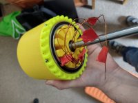
So after an extraordinary amount of time, a giant bearing I ordered on AliExpress turned up. So I knocked up a new thing to hold it and had a go

Also bought a new 3d printer... Revolutionary. Things now just fit first time.

IMG_20220602_140904775_HDR.jpg
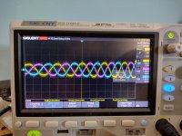
The back EMF is better still (it's actually perfect) and it's about 70kV.
IMG_20220602_145504491_HDR.jpg
Lots of torque now.

Just need to print a new hub since the old ones horrid and oval, add some m4/m5 nut holders and rewind it with a full set of coils. Think I'll add an extra turn or 2 to get a better kV... 6 turn now, I'm thinking 8 turn is optimal. Maybe I can even put it on my bike soon.
 
Back
Top