Building the Best Controller

Love the support guys! OK, let me get to it!

Quick Status:
  • Waiting for buyoff on major forum stakeholders for how to manage docs: I think we have a plan in place.
  • In the meantime I have been fleshing out hi- and low-details, and creating a list of important questions to ask.
  • I am very conscious of keeping the “Fun” in this project: Having Fun is very important for a lot of reasons as it keeps the enthusiasm and attention focused on the topic with the added benefit of little delights as we progress. If it ain’t fun it ain’t worth doing, Grrr! :wink:

Policy:
It should be said that no idea is too silly to be entertained, and in the Professional World this is pretty much the modus operandi. That assumed - governance is required to stay on top. My role is both as taskmaster and arbitrator: Build a consensus – but don’t take too long, keep our Ship of Development floating forward through the rocky straights and gale winds whilst preventing mutiny over the bounty of knowledge and option.

Schedule:
I’m in a hurry, and in fact my plans for my next ebike are arrested until we resolve fundamental issues that I believe we all share. Right now we are talking about the Controller: It’s features and functions, and divvying it up into three parts. We are taking suggestions and the door is wide open to contribution until we can sort ourselves out, dust off the furniture, confirm our marching orders, and set the ledger straight.

Today is Wednesday, August 18. I will re-present the Feature Specification as a Request before EOD (presuming this is ok…) in the Technical Reference area. The Request will be updated once each morning for one week, and that should afford enough time to capture the majority opinion.

Keep posting your thoughts and ideas to this thread!

About Noon (PST) Wednesday, August 25 – the Feature Request will close for Version 1. Then the weeding begins. Stakeholders and Contributors should identify themselves so that we can build teams.

Sobering before the Hillclimb:
I have managed a wide range of individuals from the broad walk of life, inducing and honing their focus to produce several challenging events every year as a Not-For-Profit. There will be petty grievances and prima donnas: Keep your cool, breath frequently, relax, we’re all pals, let’s play nice! :)

Anyone ever involved in public planning on a large scale understands that it is a lot like cat-herding :shock: :? :lol:

Right. Let’s get started…
 
Forgive my brevity; I do wish to address all contributions, though I may not comment on every statement.

Whiplash » 8/16-18:14 :: R/C: Duly noted and high on the List - the Spec says low to high kV; that should cover it :)

Thud » 8/16-18:36 :: Understood, thank you!

Fechter » 8/16-19:59 :: Sensorless, Trapezoidal, Regen, all in Spec and scope. Linear & Switcher: Agreed and understood.

John in CR » 8/16-20:53 :: Battery: We have a team that is focused on the BMS and I defer to them; we interface their efforts into our designs. Sensor and less: Yes, agreed. Smart Connection with Halls/Phase: Big Ask though agreed on request. Timing: Definitely a furry issue; requires addressing. Diagnostics: Error codes and recovery are part of excellence in software design; This is part of System Health/Reporting, a data stream that writes to a buffer. Performance recording: Part of System Health/Reporting; we’d need to insure that we could interface with the CA, and possibly offer an alternative for more robust reporting for third-party devices. Alarm: BWG – yeah, I like it; duly noted! Vaporware: Not! :wink:

Jsplifer » 8/16-22:06 :: Paralyze driver circuit for Monster motors: Can you expand on this request please? :?: Temp Monitor & Action, Cooling: Good points, reminds me of a MOM pack; ok – noted. Delta/Wye: Yes, a switching-signal and relay-power provision. Variable Regen: It has to be user-defined so we don’t overcharge the battery. Dual Motor: Of course; think Multimotor! Open-Source BLDC: Got it, thank you!

LFP » 8/16-23:12 :: FET Stage: Yep, needs to expand and support the bad-asses. :twisted: Needs Isolated Switching: Here’s my $5 buddy, or whatever it takes! Brain: Let’s not plan on using the Infineon because we don’t have access to the chip supply; let’s keep the options wide open as there is excellent opportunity to really make golden impression.

John in CR » 8/16-23:40 :: Upgrades to suit: Yes, exactly. Push for the Ideal: Yes, then we do the reality-check and figure out what is doable at various financial breaks.

Amberwolf » 8/17-02:17 :: Specs: I liked your specs; I think we’re in the same canoe. :)

Curious » 8/17-07:38 :: Commercial/DIY: DIY, though possibly borrowing a page from Goodrum’s BMS et al to facilitate distribution. Market Segment: We are boutique, hence why I wrote the Budweiser analogy; I think we – the small group of edge-case enthusiasts - all want to drink awesome beer! :twisted:

Fechter » 8/17-08:58 :: Optically coupled: My thoughts as well. Synchronous rectification: Noted.

Jsplifer » 8/17-16:09 :: Open Source space: Let’s allow time for ES Greybeards to comment. Open Source License: Good point! :idea:

Amberwolf » 8/17-20:45 :: Updates: Presently keeping the updated spec offline until we are affirmed where the docs are going to live. Links to new threads: Yeah, I like that approach.

Fechter » 8/17-21:58 :: Separate Thread: See my reply at 22:59 :)

Whatever » 8/18-05:39 :: 95% of the Features on ES: Agreed much has been discussed already and we can glean from that treasure trove; some innovation though is still required. Infineon: I would like to keep the door open on what brain we use. Caps & Placement: Important details to be sure; we want the best!

Thud » 8/18-05:44 :: Primary Objective: Duly noted; I set the schedule to allow for a week of comment and contribution, then we bust-a-move. Methods methods: Gotcha, will do!

Drewjet » 8/18-06:02 :: Beer: Might need to what until V1.0 ships; Thanks for the vote of confidence! :lol:

Rhitee05 » 8/18-12:20 :: Generally: You’re reading my mind! This is pretty straight-up and all you’ve said is good and wise. :wink:

That's me for Now();
~KF
 
Kingfish said:
If I understand correctly,
  • Go to the Technical Reference Area and create the specs and docs for the “Project”.
  • These docs would be kept current, with revision history, and have limited-access.
  • Continue on then with this thread, and other threads as required to complete the design and implementation.
Does this work for you? :?: :)
Yes, perfectly. Right now, only members with "Guru" status can post in the Technical Reference area. This will help prevent your reference post from getting cluttered with replies.
 
@LFP:
I don't think I understand your issue with bootstrapping the high-side supplies. It's a simple and effective solution! Your concern about protecting the FET stage is valid, but every gate drive IC I've ever seen has undervoltage detection to handle that condition. Don't mess with what works.

@LFP, Kingfish, others:
"Isolated" supplies aren't necessary for the 12V and 5V supply rails. "Isolated" only means that the output can float relative to the input ground, it does not imply any sort of noise rejection capability. The design usually provides some noise rejection, but that's not the design intent. For that $5 I can design you a non-isolated supply with better rejection at the frequencies that count (PWM frequency and harmonics).

@Fechter, KF, others:
I also think optical isolation is over-rated for this application. It's all well and good if you do want to make it isolated, but it doesn't do any good unless you isolate everything - gate drive, current sense, power, etc. - and that really becomes a pain. For the couple of bucks an optoisolator will cost you can do just as well without. Just keeping the FETs and gate drive on a separate board from the logic and analog circuits will help quite a bit.

I'm happy to offer my services to contribute. My grad school income doesn't provide very much tinkering budget, so I don't think my own controller project is going to make much headway for a while.

Among other things, I already have a design partially complete for a 100V+ input switching regulator. It uses a National switcher chip that's good to about 70V input and has a pre-regulator stage to handle anything higher. The max rating could be made as high as the group wants, it's just a matter of choosing a couple of parts with appropriate voltage ratings. 100V, 150V even, no problem. The chip I chose can supply 1A at 12V, and there are other parts available if that's not enough!

I also really like the idea of pursuing a three-board design. One board is nothing but FETs, gate drivers, current shunts, and the capacitors. A second board has the voltage regulators, all the analog circuitry for the current sense and whatever else, and probably some digital interface logic. The third board is the brains. By placing all the regulators and interface circuitry on the 2nd board, you don't even need to design the logic board - you can just use any old development board (Arduino, Atmel, PIC, FPGA, etc) and make the appropriate connections. As stated before, using separate boards will help keep EMI under control.
 
Just wanted to GREATLY support what is going on here and say that the dual or multiple motor driver is AN ABSOLUTE MUST for the R/C crowd, that along with sensorless, or the addition of halls to the motor would be an AMAZING option to have easily available to us! Wish I could help with the TECH but I can definitely give support!
 
I love it this will be the megasquirt of ev controlers!
 
People of the Planet Earth, I have posted the spec docs at this location:

Project: Building the Best Controller


Arlo, you crack me up! :lol:
Drewjet, your avatar has inspired me to post my plate...

kingfsh_plate.jpg


<sigh> I never did open that brewery :cry: but I sure got darn close! 8)
My truck is now on blocks in storage and I am saving $400 $500 $600 ? ? ? on monthly operating costs which are now redirected to...

Building the Best Controller! :twisted:
Cheers to all, KF
 
Awesome KF, but...um...you...um...misspelled your own name, missed the second I :)
 
More features for the wish list:

Have some kind of short circuit protection for the main FETs. If there is phase current measurement on each phase, a fast detector could turn off the gate drive in time to save the FET in the event of a motor/wiring short. This should trigger a shutdown mode and some kind of fault indication. Imagine a controller that you can't blow up! (at least without trying really hard)

Related: some kind of simple fault indicator display like a blinking LED.

Temperature inputs from the motor and power stage should gradually fold back the current limit rather than cut it off suddenly.
 
Awesome KF, but...um...you...um...misspelled your own name, missed the second INah! The state never gives you enough letters!
otherDoc
 
Quick Status:
  • Specs now have a home:
  • Added details in the latest version and block diagrams.
I just appended this block diagram; for some weird reason it won’t display as an image in the Reference page, so here it is presented as an Image.

3-Module-proposed.png

EDIT: Image updated on 2010-08-20

Addressing the Replies:
Rhitee05 8/18-20:20 :: Isolation & FETs on separate boards etc: Yes, I have seen this work well enough in the industry; good point. National switcher chip: These are good ideas and precede the posting of my design questions on the subject.

Drewjet » 8/19-04:15 :: Yesh, in 1993 Washington State allowed only 7 characters for a personalized plate. So, ”What do you call a Fish with no eye?” Ask yourself the question out loud. Three points to the first one who gets it right :)

Fechter » 8/19-08:36 :: Short circuit protection: oh, good one! Over-Temp failover: Yeah, I hate that cut off business; How about a user-defined minimum current with graceful degradation/restore – like a hysteresis curve?

docnjoj 8/19-18:30 :: Exactly!

Topic: Main Power Supply (MPS)
Not much traffic in the last 24 hours, so let me stir the pot and restore the boil…

In my mind, the MPS is likely the lowest hanging fruit of the whole project, and I think we should be able to knock this out rather quickly. Everything about the MPS begins with 12-15V bus; from there we can reasonably branch out to other voltages for serving up various functions, such as fueling the Brain, driving the FETs, powering the CA, and running our headlamps. I say 12 to 15V because some FET designs use 15V supply.

We also need to integrate connectivity to our BMS and our Charger, and we need to be able to turn ON or shut down power, and protect ourselves from malice and theft. Therefore the MPS board has to be robust enough to handle the majority of all typical ebike applications – as we have defined them - right out of the box and without modification.

Constraining Design Questions:
Q: What is the requested lowest power battery option we want to support: 24V, 27V, 29V, 30V, 36V? Keep in mind we need to regulate this down to 12-15V to support the BBC.

Q: What is the estimated Watt/Hr of the controlling and driving circuitry (only) relative to the target motor voltage at WOT? Do not count the 3P power running through the FETs to the motor. What are the factors that influence the consumption?

Q: What is the maximum reasonable battery voltage that can be regulated down to 12-15V?

Q: If an LM317 can reduce and regulate down 35V from V-in, would it be possible to put two or more in a step-down manner to support HVDC input?

Q: What are other alternatives to reducing HVDC to 12-15V from the maximum reasonable battery voltage, up to 225VDC, or greater?

Q: Would it make sense to abandon regulated 12-15V from HVDC and instead go with an independent secondary battery supply with supporting sub-systems?

Q: Aside from MCU and FET voltages, what would be the top-three most useful auxiliary voltages for your dream ebike? How much power do you need for each one?

Q: Would you rather see these sorts of design questions in a BBC Pole?

Thanks for your feedback, KF
 
Kingfish said:
Q: What is the requested lowest power battery option we want to support: 24V, 27V, 29V, 30V, 36V? Keep in mind we need to regulate this down to 12-15V to support the BBC.

Realistically, I don't think there's much use for EV purposes of any battery voltage below 24V. The regulator design should only need a few volts overhead to function, though, so it would be able to output 12V from a battery of 15V or so.

I think 12V should be the supply voltage. The FET drive doesn't require any more (diminishing returns) and as an accessory supply it'll be compatible with anything design for automotive use. 15V is a little too high for that.

Kingfish said:
Q: What is the estimated Watt/Hr of the controlling and driving circuitry (only) relative to the target motor voltage at WOT? Do not count the 3P power running through the FETs to the motor. What are the factors that influence the consumption?

You're referring to the power consumption of the digital circuits, gate drivers, etc? Small potatoes, a few watts at most. The National chip I like can put out 1A at 12V. I believe the Infineon regulator design generally provides 60-70 mA.

Kingfish said:
Q: What is the maximum reasonable battery voltage that can be regulated down to 12-15V?

100V or so is easy, even 150V. There's no technical obstacle to going higher, but you do have to start being careful about the spacing of traces and so forth to prevent arcing (plus safety concerns).

Kingfish said:
Q: If an LM317 can reduce and regulate down 35V from V-in, would it be possible to put two or more in a step-down manner to support HVDC input?

Yes, but it's very inefficient and generates a lot of heat. A switching design is better and not much harder to implement.

Kingfish said:
Q: What are other alternatives to reducing HVDC to 12-15V from the maximum reasonable battery voltage, up to 225VDC, or greater?

I would use a two-stage switching regulator. The primary regulator is a National LM5010HV IC. It's a highly integrated step-down switcher, inexpensive, and only requires a few external parts. It can accept an input up to 75V. The 2nd stage is a pre-regulator which brings the battery voltage down to a level the IC can accept. It's a very crude switching regulator using a PNP transistor driven by an op-amp. The op amp is configured as a comparator with hysteresis and turns the transistor on and off to keep the input voltage of the IC around the 65-70V region. A few external components provide protection and handle start-up. The maximum input voltage is determined by the PNP transistor rating, which can be quite high. As an alternate design, you could use the crude regulator to provide something like 15V, then use a 12V linear regulator from there. That would still be fairly efficient and a little simpler.

Kingfish said:
Q: Would it make sense to abandon regulated 12-15V from HVDC and instead go with an independent secondary battery supply with supporting sub-systems?

I don't think so.

Kingfish said:
Q: Aside from MCU and FET voltages, what would be the top-three most useful auxiliary voltages for your dream ebike? How much power do you need for each one?

The logic-level supply can be provided by an LM317 from the 12V rail. Placing a low-value resistor in series before the regulator will provide good noise rejection. Using an adjustable regulator like the LM317 makes it easy to set up the system for logic boards that require either 5V or 3.3V. I think it's a good idea to provide a separate 3.3-5V supply for analog circuitry. Both should only need to supply only a few 10's of mA. There's a nice little TO-92 version of the LM317 rated for 100mA that's perfect.
 
fechter said:
Have some kind of short circuit protection for the main FETs. If there is phase current measurement on each phase, a fast detector could turn off the gate drive in time to save the FET in the event of a motor/wiring short.

I would put both this and the temperature foldback as an analog circuit built into the power stage, as a per-phase item. This will:
A) prevent delays in processing the information and acting upon it, which might occur in an MCU-processed data stream from sensors, and enable faster reaction to the overcurrent/short.
B) Simplify the inter-board connections, as you wouldn't have to run small-signal analog information to an MCU board from a power board, just a "failed short circuit" or "overtemp" condition toggle line.
C) Requires less analog inputs on the MCU for these things.

Additionally, the cutoff currents and temperatures would be specific to a particular FET or power stage design anyway, and thus having the "fuse" built into the stage itself would make sense, rather than having to program the MCU with those details every time the power stage is changed. Also don't have to worry about that programming step being skipped accidentally, leaving the MCU thinking it has a different power stage with a much higher thermal cutoff, and failing to protect the actual power stage when it reaches overheat conditions.

Of course, those values could be a lookup table in the MCU rather than a manual programming stage, automatically detected by some inter-communication from the power stage as it is queried at powerup, possibly by a set of "jumper pins" on the connector that are shroted or opened at build time, or by the particilar PCB. Or something akin to PCI bus plug-n-play could be used where an EEPROM on the power board contains all this data and more; everything needed for all the parameters that could be different when running that brain with this power section, etc.

Ok, I had some ohter thoughts but i dozed off several times while typing the above and cant' remember them. :( Maybe they'll come back.
 
If you want all to build the best controller, you would need a screen display to vary parameters, one thing that comes to mind is air conditioning units, newer ones are using sensorless brushless motors, an example is fairchild FSBB30CH60 mcu driving the brushless fan motors, the newer ( in use) mcu driving the whole air conditioning unit as example is RPC555G872 which is programmable ( no idea what brand that mcu is)
( I really think concentrating on xie cheng mcu( and board mods) combined with cycle analyst will save a couple of years work).
 
For the power supply, switching is of course the only way to go if you want to have something good. The resistor option +LM317 is only used in the infinions for he same reason TO220 fets are used. It's the cheapest method to make something function.

Lots of talk about the low voltage power, but it's the high-side FET gate drive isolated supply that needs the attention. No boot-strapped crap, a real switcher to maintain a steady +10vdc source above the pack voltage no matter what sort of awful bounceing things happen. Gate control voltage must be extremely reliable. In my 800amp switching setups, the inductive voltage bounce on 1/4"x1.5" copper bus bars was so great gate voltage was getting bounced back through the conductive transition reigon for the fets on the end of the bar, and spiking below ground reference for the fet drivers, causing them to try to clamp with the intrinsic diodes, which of course just resulted in popping the driver.

If you're going to invest a few hundred bucks into a REAL fet stage, all it takes is a single split second loss of gate control for a pass-through event to occur, and now your FETs are magic smoke and plasma. The lower voltage supplies are trivial. The high side supply must be isolated from battery input voltage, and able to dynamicly move with the bounce of V+ at the fet drain legs on the fet stage. Not impossible by any means, and can heavily rely on cap stiffening to minimize the average current demand to a minimum, but still something that requires focus.
 
A floating high side supply is going to take a transformer, but it doesn't need to be very big. It does take a lot of 'glue' parts.

For the main 12v supply, I usually figure about 100ma capacity. Most MCUs run way less than this. A linear regulator is fine for going from 12v to 5v or 3.3v.

The 'Simple Switcher' chips are nice if you never go over 75v. I don't think that will cut it for many of us.
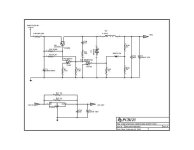
An integrated off-line switching chip will work if you're willing to use another transformer. The transformers tend to be expensive and large, however. If we can source the right one that's not too spendy, it could make a good solution. I have switching power supplies that will work from about 17v up to over 240v, so I know that's possible. That's a good range. Since the 12v supply does not really need to be isolated, it would be possible in theory to just use an inductor instead of a transformer. The Ver.2 Crystalyte controllers had something like this, but they tended to fail. It was extremely simple and something similar may work. Here's a schematic that somebody reverse engineered (sorry, I forgot who the source was)V2 Crystalyte voltage regulator.jpg

It might make sense for the main 12v supply to have excess capacity (like 1-2A) in order to run lights and accessories.

There are still many 24v systems out there, so the input voltage range should go down to 17v or so, the LVC setting for a lead-acid 24v system.

There needs to be an under voltage (and over voltage) lock out to protect the system in the event of 12v supply sag.

Having a fast analog overcurrent protection on each phase makes sense, but I don't recall seeing an example circuit for one.

On a related point, it would be nice if the controller had an integrated main disconnect relay, switch, or whatever combined with some kind of pre-charging circuit. This could be a completely separate unit, but every controller kind of needs this. Arc welding your connectors when you attach the battery is not cool.
 
fechter said:
There needs to be an under voltage (and over voltage) lock out to protect the system in the event of 12v supply sag.

Rather than just a lock-out or shut-down, a fail-safe that actively ties the FET gates low in the event of MCU power supply issues would be a pretty good idea IMO. Don't want your wheel locking-up in the event of a MCU supply glitch, or worse, a pass-through event. This could be pretty simple to do analog, and could increase safety.
 
liveforphysics said:
fechter said:
There needs to be an under voltage (and over voltage) lock out to protect the system in the event of 12v supply sag.

Rather than just a lock-out or shut-down, a fail-safe that actively ties the FET gates low in the event of MCU power supply issues would be a pretty good idea IMO. Don't want your wheel locking-up in the event of a MCU supply glitch, or worse, a pass-through event. This could be pretty simple to do analog, and could increase safety.

What if your fets are blown and shorted? I've had that happen! Maybe a control that brakes a relay to all the phase wires to relase the rear wheel?
 
Arlo1 said:
liveforphysics said:
fechter said:
There needs to be an under voltage (and over voltage) lock out to protect the system in the event of 12v supply sag.

Rather than just a lock-out or shut-down, a fail-safe that actively ties the FET gates low in the event of MCU power supply issues would be a pretty good idea IMO. Don't want your wheel locking-up in the event of a MCU supply glitch, or worse, a pass-through event. This could be pretty simple to do analog, and could increase safety.

What if your fets are blown and shorted? I've had that happen! Maybe a control that brakes a relay to all the phase wires to relase the rear wheel?

That would be great for safety, but I think most relays in the many-hundred amp power interrupting level are significantly larger than the entire size the controller could be. :(
Just fuses in any 2 of the phase leads should accomplish roughly the same goal, but in a tiny neat little package.
 
@fechter, amberwolf:
I think a per-phase cutoff circuit makes a lot of sense and would be pretty easy to implement. Use the low-side FET itself as the current-sense element and a comparator set to the appropriate threshold (probably an amp first to provide voltage gain). One plus here is that the current threshold will automatically reduce as the FET heats up and Rdson increases (choose threshold accordingly). Run the sense output as the "set" into a set-reset latch, with the reset provided by the PWM signal. This can trigger an enable pin on the driver, or some other sort of disable logic. The latch makes sure the FET is disabled for the rest of that pulse, otherwise it'll bounce on and off. A circuit like this is cheap and should react very fast. You could also include a temp sense as well, if desired.

@fechter:
The 75V limit for the Simple Switchers is not an issue because you can use a pre-regulator. This can either be linear or switching. Linear is actually not so bad, because the current is lower at the input. It's also easy to make a crude switching regulator, as I described earlier. The regulator can be very crude, since it's only an input to the LM part. The maximum input voltage can be arbitrarily high. For inputs lower than 75V, the regulator will saturate on, or for applications that will always be below 75V, simply remove the transistor and short it.

@LFP:
It wouldn't work very well to generate a single isolated supply ~10V above the battery voltage. That would subject the gate drivers to Vbatt+10 during the switching cycle, and no gate driver is designed for that. You'd have to make a discrete driver, which would be a nightmare and performance would suffer. You would have to use a separate isolated supply for each phase, which would float with the upper FET source.

Bootstrapping is a completely legit way to provide gate drive voltage - there is a reason it's widely used. There are design methods to get around the difficulties you mention. The gates can be protected from over/under-voltage, and it should include a pull-down resistor to ensure the gates are off if the driver is blown. Using an isolated supply is bulky, costly, and unnecessary.

@fechter, arlo1, et al:
Integrating a soft turn-on relay is a great idea, but those are bulky and it would be hard to accommodate different power levels. You could provide a 12V control signal for an external relay, though. That would work well and allow the use of high-current automotive relays.
 
liveforphysics said:
Rather than just a lock-out or shut-down, a fail-safe that actively ties the FET gates low in the event of MCU power supply issues would be a pretty good idea IMO. Don't want your wheel locking-up in the event of a MCU supply glitch, or worse, a pass-through event. This could be pretty simple to do analog, and could increase safety.

Yes, that's what I had in mind.
You just want to keep the FETs from turning half way on or turning on when they are not supposed to.

I'm still not sure about the main contactor. Many systems run without one. I don't like the idea of having power applied to the controller when it is not in use though. If there was a relay coil driver built into the controller that would energize the coil after precharge was complete, it might be a good feature. Like I mentioned before, this whole part may be better as a separate unit.

Using the Rds of the device as sort of a shunt to detect dangerously high current might work, but I think you'd have to gate the measurement, which makes the circuit fairly complex. It would also have to react very quickly to actually protect the silicon. Anybody have an example circuit of something like this? It may be possible to use part of the circuit board trace or bus bar as a shunt to measure the current. This could avoid the need to gate the measurement.
 
Just found this site today.
Great project. I'll be watching, and possible making suggestions.

When you start on the software, you should consider acceleration control (if you were already considering it sorry, didn't see it mentioned in this thread).
Maximize acceleration (if you have the power to spin it), and save you when you hit a patch of ice/water/oil.
Put speed sensors on the front wheel. Limit the drive to a programmable percentage more speed than that.
Could also be table based. (If the drive accelerates faster than it normally does, the tire is spinning.)
Wouldn't make much difference to the hardware, other than making sure you have plenty of inputs.

My current project is a dual motor all condition ebike for which I was planning to design a custom controller. I would want the controller to maintain the front wheels speed, to keep it from skidding or spinning on mud snow or ice, regardless of the throttle position. Considering putting a pot on the steering so the program can allow for the front tire traveling farther in tight turns (but only as a last resort)!

Yes, the Megasqirt of Magic Motors!

Bob
 
I'm away from my computer with EAGLE at the moment so I can't post a schematic, but I have a circuit designed for the fast-cutoff feature. Here's a functional description, and I'll come back and post the schematic later.

Current sense uses the low-side FET on-resistance. It requires a dual op-amp, the first to amplify the sense voltage and the second as a comparator with appropriate threshold. The input to the first op-amp also has a diode to protect it from the high voltage when the upper FET is on. The comparator output provides the "R" input to a modified R-S latch. (An R-S latch toggles the output high with "S" is high, low when "R" is high, and holds its state otherwise) The latch is unstable if both R and S are high at once, so the modification changes this by making S dominant. The PWM signal to the low-side FET is used to generate the S signal by passing through an inverter with an RC filter on the output. This makes S high when the PWM signal is low, and the RC filter provides a "blanking" time to allow for the turn-on time (keeps S asserted until the FET is fully on). The output of the latch is then used to gate the PWM signal so the PWM is disabled with the latch output is low.

Here's how it works. The PWM signal "sets" the latch each time the signal goes low (when the FET is off). When the PWM signal goes back high, the "set" is held for a short delay (probably a few us) to allow for the FET to turn on. This blanking time allows for the FET to turn on so the current measurement on Rds will be valid. Anytime after that, if the current goes above the set threshold, this "resets" the latch and disables the PWM signal, turning the FET off. The response time should be on the order of ~1 us. The PWM will remain disabled until the latch is set again when PWM goes low at the end of the pulse. Making the S input dominant and adding a small R-C delay takes care of the gating issue without adding a lot of complexity.

You might also probably want to provide some feedback to the controller, since all this would be transparent. Maybe OR the signals from each phase together and send it back as an error flag. It would also be easy to OR a temp sensor into the latch, so it could trip on either over-current or over-temp.
 
Here's a question that just occured to me:

Since these things are per-phase, do they have any feedback from one phase to another to shut off all phases, or is it only going to cut off the phase with the overcurrent / overtemp condition?

If only one phase is being cut off, then the other two could still operate during part of the cycle, and you'd get a (presumably) slighly juddery ride every time this happens, since only part of the time will the motor be receiving power to continue rotation, and always at the same parts of it's rotation (the phases that aren't shut off). That might be a good bit of rider feedback, knowing that this is caused by controller overloading or overtemp.

However, would it cause any problems with the other phases, with the extra load on them? Or simply cause their shut off circuits to activate as well?

Or would it be better to cut off all phases when one triggers?
 
My original thought was to handle the cut-off on a per-phase basis by gating the low-side gate drive, but after thinking about your question I realized a separate problem. I think we need to gate the high-side drive, so that the low-side FETs remain on to let the inductive currents freewheel and decay. If we cut off the low-side, that might cause a FET to experience avalanche failure, which is not what we want our protection circuit to do.

If we gate the high-side, we would have to OR each of the phase over-current triggers together (since the active high-side FET would have to be on a different phase than the active low-side FET. I'll have to think about it some more, but I think the best way would be to have a latch for each phase and then OR the enable/disable signals together to generate the gate signal. There might be a way to use only one latch, I'll have to think about that. It probably doesn't make a huge difference in parts or complexity, since a latch is nothing more than 2 NOR gates, so it doesn't cost much to have 3 instead of 1.
 
Back
Top