RideTheIon
10 mW
Last year I got a pair of VESCs. I had them wired up, bench tested and all, then winter came.
I thought that all I had left to do was run the motor detect with a free spinning motor and stick the case to my board.
Well, loaded up then newest BLDC tool and it said to load a newer firmware. Somehow “hw_410_411_412” seem like a good candidate so I loaded it up.
Few hour later I notice that both the controller’s DRV8302 are blow or at least that’s what the BLDC tool terminal is telling me
I'm not 100% sure that the VESCs were working fully before loading the wrong firmware. I had bench tested it with a lab power supply while the motors were linked to the wheels. The control was kind of on-or-off, but now I can only get the motors to twitch.
I only recently found out that I can query the fault codes, so the fault might have been present before.
I order new DRV8302 chips, but I thought I'd try to see if the problem might be a solder bridge, cold joint or something.
If someone’s going to remove the chips anyhow, as long as I don't hurt the traces, I can't break it more than it is now.


Based on How To Solder Your Own VESC!, pins 4-5 and 6-7 can be bridged and it doesn’t matter.
Anyway I'd like to try and clean up the smaller solder joints before sending the boards somewhere to have the chips changed.
I have a small bottle of flux and copper wick. I can borrow an adjustable temp soldering iron and heat gun.
Has anyone here fixed up a SMD board by hand? Can I apply the method that I try to soak up as much solder as possible, then put on a fresh layer?
If I work on ¼ of the chip at a time, it won't shift out of place, I guess.
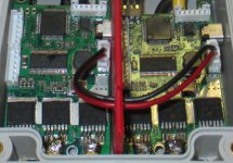
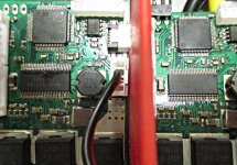
Here's a pic of my case.
I'm probably going to have heat problems, since the air can't circulate inside the case, but at least it's something to get started with.
I thought that all I had left to do was run the motor detect with a free spinning motor and stick the case to my board.
Well, loaded up then newest BLDC tool and it said to load a newer firmware. Somehow “hw_410_411_412” seem like a good candidate so I loaded it up.
Few hour later I notice that both the controller’s DRV8302 are blow or at least that’s what the BLDC tool terminal is telling me
I'm not 100% sure that the VESCs were working fully before loading the wrong firmware. I had bench tested it with a lab power supply while the motors were linked to the wheels. The control was kind of on-or-off, but now I can only get the motors to twitch.
I only recently found out that I can query the fault codes, so the fault might have been present before.
I order new DRV8302 chips, but I thought I'd try to see if the problem might be a solder bridge, cold joint or something.
If someone’s going to remove the chips anyhow, as long as I don't hurt the traces, I can't break it more than it is now.


Based on How To Solder Your Own VESC!, pins 4-5 and 6-7 can be bridged and it doesn’t matter.
Anyway I'd like to try and clean up the smaller solder joints before sending the boards somewhere to have the chips changed.
I have a small bottle of flux and copper wick. I can borrow an adjustable temp soldering iron and heat gun.
Has anyone here fixed up a SMD board by hand? Can I apply the method that I try to soak up as much solder as possible, then put on a fresh layer?
If I work on ¼ of the chip at a time, it won't shift out of place, I guess.
Here's a pic of my case.
I'm probably going to have heat problems, since the air can't circulate inside the case, but at least it's something to get started with.

