Compact Field Oriented Controller, ASI + Grin, limited run

You talking about JST-SM? if so for me in Alberta, next to where ebikes.ca is in British Columbia, buying the JST-SM is cheaper from them, then from eBay.
I was going to buy them, plus the Power Poles, 3 speed switch and some spare spokes cut to length. Instead, I am using the 4S extenders I got from HobbyKing, and I rip out one end so its a wire and pin (female) then I shove that pin into my controllers connector, and tape it good. Not ideal at all, but it will work. When I have more money I will buy his Connector bag http://www.ebikes.ca/shop/ebike-parts/connectors/conbag.html.

I do not know if you need the JST crimper tool for those connectors or not, I thought you just solder them then shove them in.
 
I HIGHLY recommend that when buying JST connectors, you buy the "pigtail" version that already has several inches of wire on the connector, with the pins/sockets already properly installed. It is very easy and fast to make a butt-splice of one wire to the next, heat up the heat-shrink...and you're done. If you need a male-female paired set, buy the extender, and chop it in half.

I have soldered and crimped several types of connectors in my time (and will continue to do so), but...as you can see from my avatar, crimping JST connectors caused me to pull my hair out in frustration. Assembling JST's could make Mother Teresa cuss. Just a thought...

6s_jst-xh_pigtail.jpg
 
Thanks for that advice, Spinningmagnets. I'm not great at soldering small things, so it probably would have killed me to try...

So the list I have is:

Battery: Anderson PP30/45 x 2
Phase: Anderson PP30/45 x 3
Hall: JST-SM 5 pin x 1
Throttle: JST-SM 3 pin x 1
eBrake: JST-SM ?? Pin x 1
Programming: Stereo 3.5mm plug (What the???!!!)

Does that sound about right? Aside from a TTL to USB cable, which I have (But goes to 9 pin serial, not a stereo plug) What else do I need?

I got the email last night that my package shipped, so I'm keen to make sure I have everything ready by the time it arrives, which could be as early as mid this week.

Thanks.
 
JST are not soldered but crimped.
Without tool, it's a mess and will fail at a high rate once installed.
Tool is here: http://www.ebikes.ca/shop/ebike-parts/repair-tools/jstcrimp.html
Way better than having too long wires, or hobbyking extensions welded to a different cable.
It's a bit of stress to cut for the first time perfectly functional controller wires, or motor wires, but once tried it's so nice and easy it's a pleasure to do.

Same for anderson PP 15/30/45
http://www.ebikes.ca/shop/ebike-parts/repair-tools/andersoncrimp.html

To build matching cables for controller will be easier than to program it with adequate tools.
 
Just got my Phaserunner - that was surprisingly quick.

Unfortunately, when I ordered the Phaserunner, I didn't realise there was such a weird TTL to USB cable. I guess I should have checked.

I can probably build one for less than $10 pretty quickly, but it seems there are several types, so it looks like I'll be paying $18 + $55 shipping. *sigh*.
 
cycborg said:
I'm still experiencing 1 or 2 faults on every ride, and I have some thoughts I want to bounce off the hive mind...

To recap, I'm using the PhaseRunner with an 8-turn Mac and 12s 10 Ah Multistars. The Mac is, of course, a geared hubmotor, and with 8 turns, the inductance is fairly low (autotune measured ~45 uH IIRC). I've been using hall-start, sensorless-run mode.

The faults almost always happen in one of two situations. First, when I re-engage the throttle after coasting. Second, when I accelerate from a stop at full throttle. In this case, the power cuts out a few seconds into the acceleration and normally comes immediately back to full strength - I'm guessing this is the hall-sensorless transition. But sometimes the power cuts and just doesn't come back.

Now, what do these two situations have in common? Clutch engagement with a moving wheel. So I'm thinking that what happens is the unloaded motor spins up with very low torque and inertia, and then the clutch grabs the wheel, and suddenly there's a spike in the torque. The controller responds by ramping up the current, and due to the low inductance, the current overshoots and trips the instantaeous overcurrent threshold before it can settle down to the current limit.

I packed my laptop yesterday and had BacDoor's datalogging feature running, and I was able to see this overshoot in the accelerating case, although the overshoot only reached 70 A (current limit is 60 A). But the datalogging interval was 1 s so I couldn't get the fine detail of the overshoot. And this didn't result in a fault; operation just continued normally.

Couple things that don't really fit into this scenario. First, in the coasting case, I'm not re-engaging at full throttle - I'm usually easing the throttle on as little as possible. So the target current is tiny, and it's hard to believe it's overshooting all the way to the threshold.

Second, I'd expect to feel a torque pulse when the current spikes before it faults, but I don't feel anything in either scenario. I just twist the throttle and nothing happens.

I'm really busy this week so I haven't had the chance to experiment with settings, but I wanted to put this out there to get feedback on my hypothesis and maybe some ideas about what direction to go. Settings are basically all defaults (aside from autotuning parameters, of course) except that the phase current limit is 60 A, current loop Ki was reduced from 70 to 10, and hall stall time was increased to 1 s.

Any thoughts?

About Instantaneous over current, i find the major related parameters:
1,Current Kp & Ki;
The bigger the current Kp, such as >0.5, the better stable the controller will be;
But, The bigger the current Kp, the more noise and vibration you will feel when you run in low speed(5~15km/h);

2,PLL Kp & Ki;
The bigger the PLL Kp, such as 8000~15000, the better stable the controller will be;
But, the bigger the PLL Kp, the more noise and vibration you will feel when you accelerate from stationary state with full throttle;

So, i try to set small Kp & Ki, for example:
Current Kp=0.05
Ki=15
PLL Kp=1800
Ki=3

Then, i got silent & smooth acceleration effect when i accelerate from stationary state with full throttle on the smooth road;
But, if run on the rough road, the phase over current must be happen!!!

This issue perplex me all the time, if your have some idea about this issue, tell me to test.
 
justin_le said:
Also, on the subject of the BAC2000 controllers. I did some more tests similar to what I'd done earlier on the BAC500 units, directly comparing the measured motor performance of the field oriented controller with a roughly equivalent 12mosfet infineon trapezoidal drive. In this case I used the V2 MXUS 3 turn motor as the control hub in order to run at a decently high RPM. The 12 fet infineon controller had a 31.5A battery current limit, so I set the motor power rating in the BACDoor software to produce the same 31.5A battery current rollback.

Here it is at 36V
View attachment 1

And at 48V


I was surprised to find that in this case no field weakening setting was required to make the unloaded RPM's match the trapezoidal case, it seems that the current firmware from ASI does this automatically as the default behavior.

At the high end of the speed range that the BAC2000 FOC has a much stiffer relationship between the RPM and load. In the 48V test case, while both motors unloaded are at about 575 rpm, once there is 20 Nm of load torque, then the MXUS motor driven with the BAC2000 slows down to about 540 rpm, while the infineon controller slows down almost twice as much to 518 rpm. So you'll get noticeably less speed drop when you hit hills running the FOC.

The performances are then fairly similar when both controllers are current/power limited at 31.5A, but as the motor slows further and further below about 350rpm then once again we see the FOC produce more torque and power output of the motor for the same input. In this case it's an extra 75-100 watts or so of motor power towards the end of the tests.

If don't use field weakening, SPWM FOC controller can't run at the same speed as trapezoidal controller;
What's the firmware version the your B2000 controller?
 
The BAC500 has a pair of wires red & black about 18 AWG; black has a piece of Heat Shrink, red is cut flush. My guess is these are part of a 12VDC supply?
 
CKs said:
About Instantaneous over current, i find the major related parameters:
1,Current Kp & Ki;
The bigger the current Kp, such as >0.5, the better stable the controller will be;
But, The bigger the current Kp, the more noise and vibration you will feel when you run in low speed(5~15km/h);

2,PLL Kp & Ki;
The bigger the PLL Kp, such as 8000~15000, the better stable the controller will be;
But, the bigger the PLL Kp, the more noise and vibration you will feel when you accelerate from stationary state with full throttle;

So, i try to set small Kp & Ki, for example:
Current Kp=0.05
Ki=15
PLL Kp=1800
Ki=3

Then, i got silent & smooth acceleration effect when i accelerate from stationary state with full throttle on the smooth road;
But, if run on the rough road, the phase over current must be happen!!!

This issue perplex me all the time, if your have some idea about this issue, tell me to test.

So in my case, where I am running a high speed motor via reduction to the wheel, I can get away with a bit higher numbers... because my motor truly never sees "low speed".... just high speed and higher speed. lol.
 
They all start at 0 rpm ;)
 
Arlo1 said:
They all start at 0 rpm ;)
nope...well...yes, but not when under load in my case..... but lets do a little math just to be sure.
I have mine on a goped not a bike.
I push off the board forward as I get on it... atleast as fast as walking speed.. thanks to my wifes love of treadmills and playing on them, I know my usual walking speed is 3.5 to 4mph.. however lets just say 3mph.
so I also know from measuring under my weight and under just its own weight that the tires compress from 10" almost exactly to 9.8 when my weight is all the way to the rear, or when I am jumping onto it.
so lets just say the wheel is 9.9 inches, going 3mph... so plugging that into a calculator gives me 101.8rpm.. or about 100rpm.
my gear ratio is 6.909... so under a normal start, my motor is already spinning about 690RPM

So most of my starts already have the motor spinning almost 700rpm. Motor is a 14 pole, so thats 7 pole pairs... so 7*700 = 4900erpm at start

Working that out, it makes sense why it always starts out easy in sensorless mode, no matter what.

this does make me wonder another question...at 4900 eRPM, how fast are most hub driven bikes going? I know they have more poles, but I dont know how many.
 
MrDude_1 said:
CKs said:
About Instantaneous over current, i find the major related parameters:
1,Current Kp & Ki;
The bigger the current Kp, such as >0.5, the better stable the controller will be;
But, The bigger the current Kp, the more noise and vibration you will feel when you run in low speed(5~15km/h);

2,PLL Kp & Ki;
The bigger the PLL Kp, such as 8000~15000, the better stable the controller will be;
But, the bigger the PLL Kp, the more noise and vibration you will feel when you accelerate from stationary state with full throttle;

So, i try to set small Kp & Ki, for example:
Current Kp=0.05
Ki=15
PLL Kp=1800
Ki=3

Then, i got silent & smooth acceleration effect when i accelerate from stationary state with full throttle on the smooth road;
But, if run on the rough road, the phase over current must be happen!!!

This issue perplex me all the time, if your have some idea about this issue, tell me to test.

So in my case, where I am running a high speed motor via reduction to the wheel, I can get away with a bit higher numbers... because my motor truly never sees "low speed".... just high speed and higher speed. lol.

My e-bike use hubmotor, it's a low speed motor where is different from mid-motor.
 
MrDude_1 said:
...

this does make me wonder another question...at 4900 eRPM, how fast are most hub driven bikes going? I know they have more poles, but I dont know how many.
Most have 23 poles, SAW2013 have 20 poles, some I had (old 406 maybe) have 8 poles.
 
A few people in this thread were curious how these controllers would cope with the astro flight inrunners.

I've been playing with a 3210 7T for a few days now. No load power at 10k rpm uses around 70w. The sensorless start has also been working really smoothly without too much trial and error. Maybe I lucked out a bit there.

Unfortunately I've been having issues with instantaneous over current faults just like MrDude. I assume the low inductance is to blame and I'm wondering whether it is possible to resolve this completely by adjusting current PI values alone. The settings I've used to achieve stability and responsiveness differ wildly to the stock settings.

Is there a way to increase the PWM frequency? Would this help?
 
spinningmagnets,

"crimping JST connectors caused me to pull my hair out in frustration. Assembling JST's could make Mother Teresa cuss."

On my latest build, I crimped 15 female, and 15 male on the BMS connections. From the handlebars to the controller and motor, I changed cable length, and/or connector type on 24 of each on the CA, throttle, thermistor, power, regen, 3 speed, and e-brake connections...and 5 for hall connections...83 in total. Giant magnifying lense, needle nose plyers, JST crimper, wire stripper, heat gun, razor knife. Lots of sweating, and lots of cussing. Got pretty good by the end. :)
 
justin_le said:
Fortunately the software has a good auto-tune feature that spins up the motor and determines the key characteristics like the winding inductance and resistance and so forth.

Sorry to be an absolute n00b, but does anyone (Not just Justin) know where this Auto-tune feature is? I think I've clicked on every tab and not found it. Is he referring to the version of the software on his website, or an older one he was playing with, when he posted this ages ago?
 
Sunder said:
justin_le said:
Fortunately the software has a good auto-tune feature that spins up the motor and determines the key characteristics like the winding inductance and resistance and so forth.

Sorry to be an absolute n00b, but does anyone (Not just Justin) know where this Auto-tune feature is? I think I've clicked on every tab and not found it. Is he referring to the version of the software on his website, or an older one he was playing with, when he posted this ages ago?

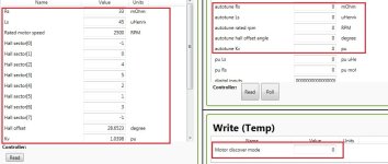
1st, Write 1 in Motor discover mode and will get Rs & Ls;
2nd, Write 2 and will get RPM, Kv, hall sector, hall offset...

tune.jpg
 
CKs said:
Sunder said:
justin_le said:
Fortunately the software has a good auto-tune feature that spins up the motor and determines the key characteristics like the winding inductance and resistance and so forth.

Sorry to be an absolute n00b, but does anyone (Not just Justin) know where this Auto-tune feature is? I think I've clicked on every tab and not found it. Is he referring to the version of the software on his website, or an older one he was playing with, when he posted this ages ago?

1st, Write 1 in Motor discover mode and will get Rs & Ls;
2nd, Write 2 and will get RPM, Kv, hall sector, hall offset...


Thanks so much :)

Is it worth while running this while I don't have the halls hooked up (only phase)? Some parts from eBay (JST-SM pigtail connectors) that were supposed to arrive yesterday, didn't. I'm just getting impatient.
 
Sunder said:
Is it worth while running this while I don't have the halls hooked up (only phase)? Some parts from eBay (JST-SM pigtail connectors) that were supposed to arrive yesterday, didn't. I'm just getting impatient.
I haven't gone through the sensorless setup, but the controller is perfectly capable of running sensorless, you might just have to do some tuning-by-feel to get the start-from-stop to work smoothly. I say go for it and report your experience for the benefit of the forum. :wink:
 
district9prawn said:
A few people in this thread were curious how these controllers would cope with the astro flight inrunners.

I've been playing with a 3210 7T for a few days now. No load power at 10k rpm uses around 70w. The sensorless start has also been working really smoothly without too much trial and error. Maybe I lucked out a bit there.

Unfortunately I've been having issues with instantaneous over current faults just like MrDude. I assume the low inductance is to blame and I'm wondering whether it is possible to resolve this completely by adjusting current PI values alone. With that said, it still provides silky smooth control and the faults are not frequent unless I ride WOT all the time.

Is there a way to increase the PWM frequency? Would this help?

U can check your rated electrical frequency in Display Only tab of Basic Motor(Sensored), normally hubmotor is about 300~500 Hz and mid-motor is near 1K Hz;
For hubmotor, 10K Hz SPWM frequency is enough; for mid-motor, the larger, the better;
However, i do not think the "low" SPWM frequency leads to phase over current,----my hubmotor is only 450Hz e-frequency;
So you have to set the bigger Kp & the smaller Ki to fight I-P-O-C, but this will leads to resonance vibration and noise, especially hubmotor.
I guess there is some design deficiency in firmware and can't do well when load change suddenly, wish ASI can notice this issue.
 
Is it worth while running this while I don't have the halls hooked up (only phase)? Some parts from eBay (JST-SM pigtail connectors) that were supposed to arrive yesterday, didn't. I'm just getting impatient.[/quote]

For mid-motor, sensorless is ok;
For hubmotor, sensorless is a torment.
 
i know im rather late to the party, but all this talk about FOC, cycles, flux, capacitors etc made me think:

flux cyclasitor
:p
Now we need to just figure out how to fuel it with 1.21 gigawats of lightning, banana skins and pepsi and were back - to 2015!

justin_le said:
will_newton said:
Just sayin'. :D

Yes! Name ideas are another things we need to sort out, since I want to call this something to differentiate it from the stock BAC800 from ASI to avoid item confusion, and we need to sort that sooner rather than later in order to CNC engrave it on the master mold so that it shows up in the castings.
 
CKs said:
Is it worth while running this while I don't have the halls hooked up (only phase)? Some parts from eBay (JST-SM pigtail connectors) that were supposed to arrive yesterday, didn't. I'm just getting impatient.

I would say that once you've got the sensorless startup mode dialed in then there is almost no point to bother hooking up the halls, unless you need that for the speedo readings of a CA device. At least I'm in that camp, since hooking up the first prototype potted unit to my ebike, I've got hall plugs on my motor and unterminated hall wires on the controller and haven't bothered to crimp on the JST's because the behavior without the halls has been perfectly fine.

sn0wchyld said:
Now we need to just figure out how to fuel it with 1.21 gigawats of lightning, banana skins and pepsi and were back - to 2015!

:lol:
 
So I have my wiring harness made for my bac2000 and every thing test out with a continuity test light. When I first connected the harness to the controller and my computer, it would not connect. I then tested to makes sure that every thing was making contact. As said the continuity test showed juice flowing where it should when it should, but it would just time out when connectig to the BAC software. Then it started crashing the BAC software Giving "windows has found a problem with this software and needs to shut it down" error. I was running the 1.5.3 version then, so I uninstalled it and reinstalled the 1.5.4 version and it is still crashing when I press connect. it crashes regardless if the controller ttl connecter is attached or not.
Anyone else having this issue with windows 8.1 and the BAC Door 1.5.4 program? if so have you been able to fix it? what did you do to fix it?

Still trouble shooting the issue, but any help would be appreciated.

I also confirmed the ttl cable is working fine by upgrading to prelim10 on my CA3 after BAC Door started crashing.
 
Back
Top