Compact Field Oriented Controller, ASI + Grin, limited run

Ok I opened that file in bacdoor using the "analyze" option, so no controller hooked up.

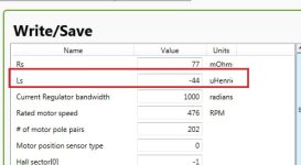
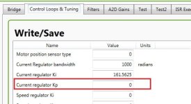
For me it shows motor inductance as -44uH. Yes negative! Under the controller debug tab -> control loops and tuning, I can see current regulator ki is set to 160 and current regulator kp at 0. I'm thinking the negative inductance value has resulted in these nonsense PI values. If you set current regulator bandwidth to 0, you can manually set the Kp and Ki. Try Ki of 2 and Kp of 0.3. You can probably leave pll Kp and Ki alone.

The other values that stuck out were the rpm and pole count values. If this motor really has 16 pole pairs, the 12:1 reduction spinning a hub at 450rpm gives an erpm of ~90000. That's very fast and probably outside what the controller is capable of. It seems much more likely that there are 8 pole pairs. Have you tried setting pole pairs at 8 and rated rpm at around 6000 instead?
 
district9prawn said:
Ok I opened that file in bacdoor using the "analyze" option, so no controller hooked up.

For me it shows motor inductance as -44uH. Yes negative! Under the controller debug tab -> control loops and tuning, I can see current regulator ki is set to 160 and current regulator kp at 0. I'm thinking the negative inductance value has resulted in these nonsense PI values. If you set current regulator bandwidth to 0, you can manually set the Kp and Ki. Try Ki of 2 and Kp of 0.3. You can probably leave pll Kp and Ki alone.

The other values that stuck out were the rpm and pole count values. If this motor really has 16 pole pairs, the 12:1 reduction spinning a hub at 450rpm gives an erpm of ~90000. That's very fast and probably outside what the controller is capable of. It seems much more likely that there are 8 pole pairs. Have you tried setting pole pairs at 8 and rated rpm at around 6000 instead?

It actually only has 8 pairs, 16 magnets. The motor inductance was entered from the auto tune. I did find it a bit odd to be negative values, when the manual was all entering positive values, but that's what came back.

It could be a couple days until I get another go at this, but thanks for your help. If you wouldn't mind checking back in, in a week (Assuming you don't check more regularly anyway), I should have had a bit more time to play with it again.
 
Sunder said:
It jerks all over the shop, and triggers the current error even on no load.

I'm hoping to do a bit more tuning tonight. I set a limit of 800w on the bike, and my top speed has definitely dropped from the old 1000w trapezoidal controller I had, and sudden changes of throttle sometimes makes the motor give a "clack" noise and lose power for a few seconds. I'm hoping I can crank up the power and see if I can increase the transition of power a little more smoothly to avoid that noise.

I'll get that XML file up as soon as I can - hopefully in about 6-7 hours from now.

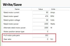
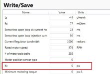
There is something wrong in your XML, and i think the wrong pole pairs, Gear ratio and Kv make the controller disordered.
Error 1.jpg
Error 2.jpg
Error 3.jpg
Error 4.jpg
 
Thanks Guys. Those figures were cobbled together from copying other Q100 (non-H) motors, auto-tune and advice from the BAC500 manual. I don't actually understand what most of those values represent (aside from the obvious ones).

Can anyone give me some suggestions on how to either figure out those values, or some known values I should enter?

When I entered 8 pole pairs, 12.6 ratio, it didn't work, even when I raised the RPM (260rpm / 36v * 67.2v *12.6). I can give it another shot now that I've got it working though.

One of the pieces of bad news though, is that I've destroyed the clutch by all the jerking, I think. It rode perfect yesterday, provided I rolled on the power very gently, but today, I'd have to give it one or two goes towards the start of the ride. By the end of the ride, it was not engaging more than it was engaging.
 
Sunder said:
Thanks Guys. Those figures were cobbled together from copying other Q100 (non-H) motors, auto-tune and advice from the BAC500 manual. I don't actually understand what most of those values represent (aside from the obvious ones).

Can anyone give me some suggestions on how to either figure out those values, or some known values I should enter?

When I entered 8 pole pairs, 12.6 ratio, it didn't work, even when I raised the RPM (260rpm / 36v * 67.2v *12.6). I can give it another shot now that I've got it working though.

One of the pieces of bad news though, is that I've destroyed the clutch by all the jerking, I think. It rode perfect yesterday, provided I rolled on the power very gently, but today, I'd have to give it one or two goes towards the start of the ride. By the end of the ride, it was not engaging more than it was engaging.

Kv---Use default value: 1;
For Pole pairs & Gear ratio, pls high light your motor(Mid-BLDC or Hubmotor) brand & model, maybe someone use the same one.
 
CKs said:
Kv---Use default value: 1;
For Pole pairs & Gear ratio, pls high light your motor(Mid-BLDC or Hubmotor) brand & model, maybe someone use the same one.

I am using a Q100H - it has 8 pole pairs, and a 12.6 gear ratio.

What is the likely "Ls" value and Current Regulator Kp and Ki though?
 
Sunder said:
CKs said:
Kv---Use default value: 1;
For Pole pairs & Gear ratio, pls high light your motor(Mid-BLDC or Hubmotor) brand & model, maybe someone use the same one.

I am using a Q100H - it has 8 pole pairs, and a 12.6 gear ratio.

What is the likely "Ls" value and Current Regulator Kp and Ki though?

Normally the Ls is xx~xxx uH for BLDC(hubmotor) we use, u can try 30 uH & Current Regulator bandwidth=1000 fist time;
Then follow below step:
First, set #of motor pole pairs=8, Gear ratio=12.6, Kv=1 and Save to Flash;
Second, Write 1 to Motor discover mode; If get Rs & Ls, Write and Save to Flash;
Third, Write 2 to Motor discover mode; If get autotune rated rpm, autotune Kv & autotune hall sector, Write and Save to Flash.
 
What's kp? I might have to add that stuff (don't have my laptop with me). Could that relate to the instantaneous over current fault? My halls sound like they're mapped right but I keep getting an instantaneous phase over current fault after a few seconds or at hard throttle.

I'm using the lightningrods small block and as far as I know it's 12 poles and running around 30:1 to the wheel. Seems like I get slightly different auto test values day to day. Sensorless works, but jittery and not ideal I just can't get past that fault on sensored.

Ill try and remember my xml tomorrow. That may help
 
r3volved said:
What's kp? I might have to add that stuff (don't have my laptop with me). Could that relate to the instantaneous over current fault? My halls sound like they're mapped right but I keep getting an instantaneous phase over current fault after a few seconds or at hard throttle.

I'm using the lightningrods small block and as far as I know it's 12 poles and running around 30:1 to the wheel. Seems like I get slightly different auto test values day to day. Sensorless works, but jittery and not ideal I just can't get past that fault on sensored.

Ill try and remember my xml tomorrow. That may help

Too small current Kp will lead to I-P-O-C when load suddenly change.
Assume u have offered the right parameters of motor to controller,
Just try:
1, Set Current regulation bandwidth with 1000, or bigger(2000~3000) to auto-get current Kp & Ki;
2, Set Positive motoring torque ramp with 150 ms.
 
CKs,

Would you mind taking a moment to explain what "I-P-O-C" means?

And better still, explain what Kp and Ki do?

I googled the terms, and it explained what they mean, but not what they do, and how they affect the motor.

Thanks so much for spending the time here.
 
Would you mind taking a moment to explain what "I-P-O-C" means?
I use acronym to take the place of Instantaneous Phase Over Current :p

And better still, explain what Kp and Ki do?
I googled the terms, and it explained what they mean, but not what they do, and how they affect the motor.

The controller software use PI control policy(Current regulator Kp & Ki) to control 3 phase sine-wave current output response accuracy;
The bigger the Kp, the more accuracy the current output;
While, the bigger the Kp, the more vibrating the current output;
The smaller the Ki, the more accuracy the current output;
While, the smaller the Ki, the more vibrating the current output;
Good Kp & Ki setting means silence in low speed and no I-P-O-C when load suddenly changed;
So, if u can accept motor's noise and vibrating in low speed, just try bigger Current Regulator bandwidth.

More information about PI control u can check Dave's blog from Ti's website:
http://e2e.ti.com/blogs_/b/motordri...atch=PI CONTROL&tisearch=Search-EN-Everything
 
Got some time to play with it last 4 weeks...
In a word, impressive !

Near silent, to start. Silent when running under constant load in the 100-500 W range, slightly whining at 13 kHz under full load, meaning 1000-2200 W depending on conditions of speed, slope, weight and battery state of charge. Total noise level way lower than before, no question about it. No more motor noise, just controller PWM.

But the best is yet to come.
After many trials, it appears the smoother ride allows me to clearly lower current in all 3 modes for the same net result, leading to a huge gain in consumption. On one of my daily drives, 14 km with approx. 450 m of negative and 450 m of positive elevation, I was able to move from 8 to 5.5 Wh/km in slow mode, and from 11.5 to 8.5 Wh/km in fast mode, for same travel time and effort.
Motor is running at lower temp, casing is around 42°C instead of 50°C with Infineon controller, and everything is much smoother.

I only lost ability to spin tyre under full load at start, now everything is smooth it starts strong but no spinning anymore. Price to pay for a well done and balanced system, it's way more efficient and reasonable, but a bit less fun sometimes. ;)
Really happy with this small beast, even if it was a pain sometimes to configure.

Throttle and brake management was a long time issue, as you have to put enough error margin to allow regen to kick in without going into throttle error.
My way: Throttle out on CA3 0.9 to 3.6 V, in BacDoor deadband 0.2 V, error 0.9 V, brake from 0.9 to 0.2 V. Braking torque 50 %. Brake out at 0.2 V in CA3. This allows throttle error to kick in for negative voltage or higher than 4.5 V, safe then.
 
cavallo pazzo said:
Got some time to play with it last 4 weeks...
In a word, impressive !

Near silent, to start. Silent when running under constant load in the 100-500 W range, slightly whining at 13 kHz under full load, meaning 1000-2200 W depending on conditions of speed, slope, weight and battery state of charge. Total noise level way lower than before, no question about it. No more motor noise, just controller PWM.

But the best is yet to come.
After many trials, it appears the smoother ride allows me to clearly lower current in all 3 modes for the same net result, leading to a huge gain in consumption. On one of my daily drives, 14 km with approx. 450 m of negative and 450 m of positive elevation, I was able to move from 8 to 5.5 Wh/km in slow mode, and from 11.5 to 8.5 Wh/km in fast mode, for same travel time and effort.
Motor is running at lower temp, casing is around 42°C instead of 50°C with Infineon controller, and everything is much smoother.

I only lost ability to spin tyre under full load at start, now everything is smooth it starts strong but no spinning anymore. Price to pay for a well done and balanced system, it's way more efficient and reasonable, but a bit less fun sometimes. ;)
Really happy with this small beast, even if it was a pain sometimes to configure.

Throttle and brake management was a long time issue, as you have to put enough error margin to allow regen to kick in without going into throttle error.
My way: Throttle out on CA3 0.9 to 3.6 V, in BacDoor deadband 0.2 V, error 0.9 V, brake from 0.9 to 0.2 V. Braking torque 50 %. Brake out at 0.2 V in CA3. This allows throttle error to kick in for negative voltage or higher than 4.5 V, safe then.
what motor are you using? and at what voltage?
 
700 phaserunner.JPGIt's an old nine continent, RH205 serie A from 2008 probably.
A 2808 to follow current naming.
It's on a 37-622 wheel, giving a relatively long gearing.
Batteries are two old (2011) 14s6p Samsung 22p cells, giving 51 V 13.5 Ah each. After a bit more than 4 years, I still have 20-21 Ah instead of 27 Ah (theory) or 24 Ah (real world) thanks to partial charge.

This motor is built with embossed steel plates as stator, not cast aluminium, thus noisier if driven with less than pure waweform.
Evolution from trapezoidal to FOC was a godsend for this baby.
 
cavallo pazzo said:
Got some time to play with it last 4 weeks...
In a word, impressive !
Near silent, to start. Silent when running under constant load in the 100-500 W range, slightly whining at 13 kHz under full load, meaning 1000-2200 W depending on conditions of speed, slope, weight and battery state of charge. Total noise level way lower than before, no question about it. No more motor noise, just controller PWM.
...After many trials, it appears the smoother ride allows me to clearly lower current in all 3 modes for the same net result, leading to a huge gain in consumption. On one of my daily drives, 14 km with approx. 450 m of negative and 450 m of positive elevation, I was able to move from 8 to 5.5 Wh/km in slow mode, and from 11.5 to 8.5 Wh/km in fast mode, for same travel time and effort.
Motor is running at lower temp, casing is around 42°C instead of 50°C with Infineon controller, and everything is much smoother.
...Really happy with this small beast, even if it was a pain sometimes to configure.

Hey Cavallo and thanks a lot for detailing and sharing those results, which are even a surprise to me on the consumption front. Glad to see that this controller has really made a difference.

The configuration setup with some motors is definitely a bit of a pain and learning curve for sure and I thank all those with some understanding who've been posting here helping people out with the tuning. I'm really hoping that by mid-December we'll be ready to have examples of our own interface/setup software to replace the Bacdoor package for all the basic configs.

We have another 1000 pcs of the bare controller PCB's here at Grin for our 2016 production and still sorting out a number of hardware refinements, which includes an integrated on/off push button in the potting, fwd/rev control line, the sending of a CA-DP speedo pulse even with no halls plugged in, a custom made ultra-high strand count motor phase cable with teflon insulation and 3.4mm^2 copper, a custom 4 conductor high strand flexible battery cable (2 x 13g for the input power, and 2x18g for the charging/auxilliary leads if you want other devices to take advantage of the shunt). So if people are wondering that's where things are going with this project and I'll be posting more detailed updates when the next phase prototyping is a bit further along.
 
justin_le said:
We have another 1000 pcs of the bare controller PCB's here at Grin for our 2016 production and still sorting out a number of hardware refinements, which includes an integrated on/off push button in the potting, fwd/rev control line, the sending of a CA-DP speedo pulse even with no halls plugged in, a custom made ultra-high strand count motor phase cable with teflon insulation and 3.4mm^2 copper, a custom 4 conductor high strand flexible battery cable (2 x 13g for the input power, and 2x18g for the charging/auxilliary leads if you want other devices to take advantage of the shunt). So if people are wondering that's where things are going with this project and I'll be posting more detailed updates when the next phase prototyping is a bit further along.

These sound like awesome updates. I am glad this is not going to be a 1 run thing. I want one for my wifes bike once shes ready for it.
 
Do you plan to incorporate the ca programing software into your version of the backdoor software? It would be awesome if you could setup the software to output ca settings relative to the bacdoor settings that are input. Such as I set the throttle min voltage in backdoor and it would either set the parameters of the ca to match or at least fill out a table telling what the ca settings should be.
It would greatly simplify setup and remove alot of potential for error.
 
One more thing: regen changed a lot.

First chinese controller, set to 22 A, had a max regen around 500 W. Almost useless above 5 % slope
Old 2011 controller, 40 A model, was able to push around 650-700 W.
Phaserunner, not knowing how to set it, was programmed at 50 % to evaluate.
Wow ! More than 1200 W with ease, even strong in a 8 % slope, will have for the first time of my life to decrease it a bit, to 40 % probably.

Think it's about time for variable regen, for a first try I'll use a potentiometer to do a linear divider, program CA to 0.8 V and set my divider to have a range of 0.2 to 0.8 V, with a max at 50 % like now and a min at maybe 10 % depending of brake start voltage setting.
Such a strong regen could replace brakes for almost all uses, especially in winter as regenerative braking is less prone to wheel blocking than classical brake. Especially with a settable braking torque.
 
mjayt said:
Do you plan to incorporate the ca programing software into your version of the backdoor software? It would be awesome if you could setup the software to output ca settings relative to the bacdoor settings that are input.

Hmm, we hadn't really thought about that. My plan in some sense was to really standardize and fix the throttle mapping on the Phaserunner so that it could be counted on to have a certain sensible mapping (like 1.15 - 4.0 V for throttle, 0.85-1.15 V for deadband, and <0.85V for regen) and take this as a given. Since yeah, being able to independently control both the throttle mapping on the CA and on the Controller results in too many possibilities and makes difficult to offer standardized CA or Phaserunner settings for people to download.

Anyone who for some reason needs custom phaserunner throttle ranges could always do that with Bacdoor, but we'd try to enforce a a standardized set of ranges with our own software to eliminate this extra variable.
 
cavallo pazzo said:
One more thing: regen changed a lot.

First chinese controller, set to 22 A, had a max regen around 500 W. Almost useless above 5 % slope
Old 2011 controller, 40 A model, was able to push around 650-700 W.
Phaserunner, not knowing how to set it, was programmed at 50 % to evaluate.
Wow ! More than 1200 W with ease, even strong in a 8 % slope, will have for the first time of my life to decrease it a bit, to 40 % probably.

Ha yeah. When I switched to the Phaserunner from the infineon style controller my average % regen on my commutes increased from ~4% regen to ~6% regen, and don't have it set all that strong yet so I still engage mechanical when braking to a stop. Out of curiosity, are you monitoring your motor temperatures during these long downhill regen sessions?

Think it's about time for variable regen, for a first try I'll use a potentiometer to do a linear divider, program CA to 0.8 V and set my divider to have a range of 0.2 to 0.8 V, with a max at 50 % like now and a min at maybe 10 % depending of brake start voltage setting.

I think sooner than not we'll have some test versions of a V3.1 CA firmware with the proportional regen features built-in. Me and Teklektik are starting to tackle this right now. The plan is that you'll set the brake-out volts to be the output when you just squeeze the brakes, and then you can use the throttle to decrease this all the way to 0V, much like we have done with the Grinfineon motor controllers. This gives variable regen using existing hardware on your bike without the need for a proportional ebrake sensor or extra potentiometer.

There's another method I've been dying to try for many years which is reverse pedal activated regen. Might be gimmicky but for people running PAS systems it could be pretty intuitive too, and then a faster backwards pedal = higher regen intensity. In any case for sure by the time we have the upcoming production of Phaserunners underway there will be a matching set of CA3 firmware to take full advantage of the capabilities.

Such a strong regen could replace brakes for almost all uses, especially in winter as regenerative braking is less prone to wheel blocking than classical brake. Especially with a settable braking torque.

Robbie here has been (somewhat recklessly I dare say!) running with only regen and no mechanical brakes on his commuter bike for over a month now since he hasn't gotten around to fixing a broken brake cable and the regen has been good enough. IIRC he has his regen close to 100% of max phase current. It really is much more effective than traditional rim brakes in the rain, but you're hooped if the battery ever gets disconnected.
 
justin_le said:
Robbie here has been (somewhat recklessly I dare say!) running with only regen and no mechanical brakes on his commuter bike for over a month now since he hasn't gotten around to fixing a broken brake cable and the regen has been good enough. IIRC he has his regen close to 100% of max phase current. It really is much more effective than traditional rim brakes in the rain, but you're hooped if the battery ever gets disconnected.

:shock: hope he doesnt get a stuck throttle!
 
Robbie here has been (somewhat recklessly I dare say!) running with only regen and no mechanical brakes on his commuter bike for over a month now since he hasn't gotten around to fixing a broken brake cable and the regen has been good enough. IIRC he has his regen close to 100% of max phase current. It really is much more effective than traditional rim brakes in the rain, but you're hooped if the battery ever gets disconnected.

This is Robbie's opportunity to invent the bicycle world's version of the "parking/emergency brake". Something more sophisticated than sticking your foot into the spokes of the front wheel, I'm hoping.
 
Back
Top