• Howdy! we're looking for donations to finish custom knowledgebase software for this forum. Please see our Funding drive thread

Connecting EM3EV to A2B. Reuse parts?

djrobb

1 mW
Joined
Apr 13, 2020
Messages
10
Hi, I’m new to the forum and appreciate your help. I searched through the forum for an answer but didn’t quite find the info i needed.

I’m replacing the 36v battery on my A2B Alva+. I’m replacing it with a new aftermarket EM3EV Super Shark battery. The picture is after i disassembled the stock battery pack and shows the stock battery electronic internals minus the old Lithium batteries. There is an on/off push button switch, a 3 pin XLR charging port and a Rosenberger magnetic connector to the bike.

This magnetic connector has the obvious positive and negative wires. But it also has a small blue and small green wire and I’m unsure what these are for. Im worried they are Important! The stock bike has 3 assist modes, a key fob, display and a throttle and I’d like to retain those functions if possible.

I’m trying to figure out how to connect the new EM3EV battery which only has positive and negative. I’m unsure if I should connect the new battery directly to the bike (discarding everything in the picture) or I should reuse some components from the picture for the sake of the mystery green and blue wires. I appreciate your help!

Option 1) discard stuff In picture, ignore blue and green wire, wire new connector to positive and negative on bike.

Option 2) reuse Rosenberger magnetic connector, ignore blue and green wires, discard rest.

Option 3) retain everything and wire the new battery to the positive/negative on the circuit board bullet connectors. I think this would mean I have two battery management systems though (old one pictured and new one in EM3EV battery)

Thank you thank you thank you!
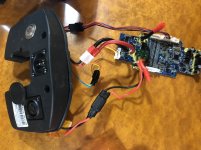
A977ED3B-36C2-4A02-ABE5-6BA11FDAD787.jpeg
 
Can we get a clearer close up of where that JST connector goes into the board? preferably with flash? that whole blue board looks like a BMS board with per cell balancing but it almost has too many components, maybe due to some communication things.

they probably arent:

- current draw
- temperature
- voltage reading

a thing it could be

- BMS authentication for A2Bs controller?(i.e. hardware identification/DRM so that you HAVE to use their batteries)

if above is the case, youd have to run your balance wires from the old battery to the new one making this a significantly more difficult swap. The other option is hoping another BMS would work, bu this is a swing in the dark without more experienced input or someone having done it before. the alternative to rewiring your brand new pack from top to bottom after ripping the outer insulation off would be this site( I have no experience with them it came up on my first google search) https://ebikemarketplace.com/products/a2b-li-ion-electric-bike-batteries?variant=39450300293.
 
Thanks! Here are some additional pictures. It looks like the batteries are fully charged. So I think I am going to take the BMS out of the wiring for now and see if the bike will run. If it runs, I guess I'll just get a different BMS. The two communication wires alongside the power wires were definitely plugged into the stock BMS so they do something, will just have to figure out what doesn't work anymore.

https://imgur.com/1R9KxCy
https://imgur.com/5rlmVTT
https://imgur.com/xBM5g8k
https://imgur.com/apeINbq
https://imgur.com/CQzC9ry
https://imgur.com/CjTTII4
https://imgur.com/PvnxRIQ
https://imgur.com/YpUI1Oq
 
I checked the images you sent, Thanks for providing them! it looks like a group of diodes, ill have to check some things out, see if I can find a generic BMS that has a similar circuit to the one you'd have. If I were in your position, Id Hail Mary it and just connect the em3ev battery straight to the connector and see if it runs.

Also, if the cells are showing nominal voltage or higher, it sounds like the BMS may be dead which could spell out bad news depending on what those two smaller wires do.

Ill keep you posted.
 
Thanks so much, I really appreciate it. I'll try and connect the new battery directly and see what still works. I am waiting for some XT60 connectors to come in the mail so I am hoping to try this on Tuesday. If you find anything please let me know!
 
I found this thread which may help some, for a different battery from the same manufacturer.

https://endless-sphere.com/forums/viewtopic.php?t=87115
 
Just an update. With the BMS removed from the battery pack the bike has all the essentials working including the throttle, mode selector and assist. The battery capacity gauge on the bike doesn’t work and it seems to forget settings when the battery is disconnected. Those things are no big deal. Next I’ll buy an aftermarket BMS and see how that goes.
 
Sounds good, its great to hear it working! You could run a DC power meter instead of a battery gauge, probably much more useful tbh.

bayite DC 6.5-100V 0-100A LCD Display Digital Current Voltage Power Energy Meter Multimeter Ammeter Voltmeter with 100A Current Shunt https://www.amazon.com/dp/B013PKYILS/ref=cm_sw_r_em_apa_i_AEmTEb3ADEMMR
 
Ok. I’ve got the BMS but am a little unsure of the wiring. Can someone please let me know if I understand this right?

Wiring to the bike:
The positive plug that goes to the bike connects to the last battery (positive side).

The negative plug that goes to the bike is soldered to the c- on the BMS

Wiring to the charger:
Not sure where the positive from the charging cable goes.

Negative plug that goes to the charger gets soldered to p-?

Battery pack negative terminal is soldered to b-?

https://imgur.com/bsIV05e
 
Uh oh. Also. Do the positive wires in the harness have to be in order? When I plug the harness into the BMS and nothing else the BMS starts to smoke and that seems bad. I’m fairly sure I have the negative wire in the correct spot in the harness but I didn’t give any special consideration to the order of the positive hookups.
 
If you got smoke, you'll need a new BMS.

Stuff is now damaged in a way you can't know or predict what will happen with later on, even if it *appears* to operate now. (for instance, it may not sense LVC or HVC, allowing overdischarge or overcharge of cells, or it may have balancers that either can't turn on or are permanently on, creating imbalance or even killing groups of cells by constantly discharging them).


The order of the wires should be provided by the BMS manufacturer (or seller), if it is not marked on the BMS itself.

You can *guess* that they must go in the order from most negative to most positive, starting at the pin closest to the negative battery wire, but unless you can trace out the PCB and figure out the circuits, you can't know for sure that's how it's wired. :(

You don't want to experiment to find things out, because you'll damage things if you do this, because of the voltage potentials across inputs, vs what they were designed for.

Some of them even require that you skip some input pins (because they are wired together, and you'll short out your cells).


For the B- P- C- connections, again you'd need to check the manufacturer diagram, as they are not always marked correctly. But if you look at the many "how do I wire my BMS" threads, you'll see how the majority seem to be wired, with C meaning charge (input), P meaning power (output), and B meaning battery (input).
 
Thanks so much for your advice and response. I did purchase a new BMS when that one smoked and I’ll try again. I reordered the pins for the BMS putting them in order. I watched a video on wiring a BMS which I clearly should have done before! Will post how the new one works out. Thanks again.
 
Back
Top