I would like to commend you for your patience. It seems that the wiring documentation for your particular controller model is a bit sketchy. I unfortunately have been not able to find a correct match.
I wish I had Visio or something to draw out a diagram as that would be helpful for me to try and follow what needs to be connected to what and where..
You don't need anything fancy... just a white sheet of paper with a high contrasting marker. Do the best you can, label everything, take a picture and upload.
")
Please disregard my previous post's solution as after more research I have a different view at this time. Here is why...
Often controller manufactures will include an "ignition" circuit to make it easy to do what you are attempting to do.
In this example, this single wire and therefore the circuit. Is energized by providing full battery+ power to the "ignition" wire.
But it appears to me that Sabvoton has taken a different approach. Conclusion reached by looking over several similar wiring diagrams and product description pictures.
Your Sabvoton model is SVMC7280
-M,
correct? Referencing your description page pictures you posted above.
It looks like their ORANGE "ignition" wire, instead of an input wire. Is actually just a full battery+ wire out.
This provides battery+ voltage to a connector that has a jumper wire that is required if a switch (or key switch in your new throttle) is
not used, then on to your display, and possibly the alarm system.
To verify my theory, proceed as follows...
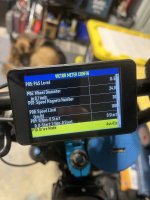
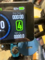
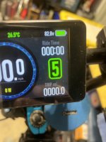
Since you haven't mentioned your testing knowledge or ownership of a multimeter. I'll continue by having you use the throttle's digital voltmeter for testing. As such, leave it connected for now to just the 3 low voltage wires during the steps below.
Isolating the high voltage wires till testing requiring the use of.
If you have and know how to use the meter... by all means do so.
Full battery+ voltage is present and expected in this testing, use caution and do not short exposed connections or wiring.
Follow these instructions step by step. If something not found or acting as described or instructions are not clear enough, stop there and ask for clarification before proceeding. And upload your hand sketch diagram when available.
1) Battery off, look for the two-pin connector that has the single ORANGE wire (labeled "ignition") from the controller going into it. On the opposite side connector from this, look for a single wire loop on that pin that jumps to the other pin. The other wire on the same side as the single ORANGE "ignition" wire, will eventually go to the display pin #1.
2) Battery on, everything works as it always has. (just no key switch operation...)
3) Battery off, remove jumper connector as found above (the loop), battery on, nothing works.
4) Battery off, reconnect jumper loop, cut the jumper wire in the middle and strip both ends keeping them
carefully isolated as needed.
5) Key switch off, Battery on, carefully touch throttle's BLUE wire to where the single ORANGE wire from the controller connects to. You should get full battery power voltage displayed on the throttle meter.
6) Battery off, connect the throttle's YELLOW wire to the wire you just tested. Connect the throttle's BLUE wire to the other wire at that connector. (The one that continues to the display.)
7) Battery on, key switch off, nothing works. Key switch on, throttle's voltage meter lights up and displays correct voltage. Press the power on button of the display. Everything works as desired. Great, testing complete.
Make the connections cleaner, insulated, permanent, and more secure as desired.
Hopefully you made it all the way thru, if not please post where problem appears.
Couple other things while I'm thinking about it...
The two BLUE wires in your picture holding them, what are they, and why are they like that? (I'm thinking speed limiter.)
The description of your controller states that the
default throttle setting is a potentiometer type throttle. (0 to 5vdc output.)
Is your new throttle a potentiometer type, if so no problem. But if it's not, you will have to change the programming for your new throttle that probably has a hall sensor. But if the old throttle is a hall sensor throttle, this has hopefully been changed already, and your good to go.
To understand the differences in throttle types, and why it matters, see this post...
Guide to Hall Sensor Throttle operation, testing, and modification. - Electricbike.com Ebike Forum
Good luck,
T.C.