Controller diagnosis

docbong85

1 µW
Joined
May 29, 2023
Messages
2
Location
Radium, BC
Hoping someone can help me troubleshoot, as
I'm fairly new to EVs but not entirely new to electronic/circuit board repair.
Here's the situation:
Scooter was brought to me with a non responsive LH-100. Determined plugs for charge port that were replaced by previous owner were different pinout, and so battery wasn't charging. Discovered in troubleshooting that the BMS had some blown FETs, so it was replaced with a BT JBD model.
Finally figured out how to get it configured to charge/discharge, and fairly certain amps, volts, etc all within listed spec of battery (it's a 60v setup).
Problem is, shortly after getting it all top balanced, configured and running, after the first 10min ride the lh-100 went dead. Found some burnt circuitry, and ordered replacement. Began looking at controllers, and that's where I get really stuck.
All the documentation and advice I've come across on the web states good/bad values for resistance testing across phase to ground and phase-power, and those being steady solid numbers.
Problem I'm having when testing is I don't get steady readings, clearly capacitors are being charged by the meter during test. Hard to interpret if there's shorts or blown FETs or what.
Is it a diode maybe?
Oh, and I should add the replacement LH-100 burned up too. So it's as if the controllers are overclocking, overclocking, or bypassing regenerative current or something.
Please help
 
Some things that may help us help you diagnose the problem:

What scooter is being worked on? What kind of drive system does it have? (direct drive hubmotor, geared hubmotor, middrive, etc)

Is this the "LH-100" you're referring to?
or is it this one?
or is it some other one?

How exactly are you doing the FET tests, including your meter settings and lead connections?

What readings do you get after the (caps?) have been charged?

What circuitry burned on the first LH-100? What burned on the second? Under what ride conditions?
 
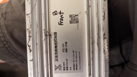
It's a Chinese clone Laotie ti30 with dual DD hub motors powered by Yunli controllers, and yes it is the first referenced LH100(60v).
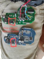
First throttle failure was not an obvious burned section or failed component, but second fail was an arc hole blown right through of one of the ICs (attached photo, if exact pn needed, will disassemble again and inspect).
FET tests are as described in this link:
https://www.google.com/url?sa=t&sou...sQFnoECBAQAQ&usg=AOvVaw1pX7eWCo1XUmQrZQ2uXTMh

With a Klein auto-ranging clamping ammeter/multimeter in both continuity (diode) and RΩ settings.
Once caps reach charge state (numbers stop cycling up or down, depending on polarity), continuity is lost and infinite resistance is shown.


As far as riding conditions, I wasn't present. Scooter is owned by a friend who's not technically capable (or more just frightened) with electronics. So, he brings me all his broken electrical toys with vague descriptions like: "I dunno, I was riding it to the store. I turned around. It wouldn't turn on."
No idea if it happened while under load, after stopping, during a turn, at what speed, how hard of brake applied, etc.
 

Attachments

  • 66953-1280~2.jpg
    66953-1280~2.jpg
    383.6 KB · Views: 12
  • PXL_20230603_020712543.jpg
    PXL_20230603_020712543.jpg
    1.7 MB · Views: 10
Last edited:
First throttle failure was not an obvious burned section or failed component, but second fail was an arc hole blown right through of one of the ICs (attached photo, if exact pn needed, will disassemble again and inspect).
That looks like a voltage converter or regulator in TO220-5 format. If it's like the 7223 (random example), it's only good up to 45v. There are some other ones out there that are good for higher voltages like the 2596HV which is good ot 60v (but a 60v battery actually charges up to 68v+), but there are many crappy versions and counterfeits out there, commonly used in cheap ebike stuff and other devices like these
that can't actually handle the voltage the original part is rated for, and they usually fail catastrophically like the one you have there.

Is the scooter like this?


FET tests are as described in this link:
https://www.google.com/url?sa=t&sou...sQFnoECBAQAQ&usg=AOvVaw1pX7eWCo1XUmQrZQ2uXTMh

With a Klein auto-ranging clamping ammeter/multimeter in both continuity (diode) and RΩ settings.
Once caps reach charge state (numbers stop cycling up or down, depending on polarity), continuity is lost and infinite

Just curious, since the failures you specify are in the throttle unit rather than the controller: Were you testing the controller's phase FETs, or the throttle/display unit?

The ebikes.ca document is usually used for testing the phase FETs of the controller (with the motor and battery disconnected from the controller).

If you're testing the controller phase FETs, I don't know a reason they would do what you see except when testing across the battery bus positive and negative.

If the FETs are shorted, a DD hubmotor will be harder to turn than normal (the more shorted FETs, the harder to turn), whether the controller is powered on or not, but still plugged into the motor's phase wires.

As far as riding conditions, I wasn't present
Generally I recommend always asking for failure conditions when troubleshooting something, when this is the case. Knowing what happened just before the failure and the conditions it happened under often points directly to the failure cause, and can help you fix it in a way that won't let that cause create that failure again.

Without knowing when and how it happened you usually won't know why it happened, so any fix you do has a significant chance of being just a band-aid until the next time the same thing happens...which will be just as like as not to cause it again.
That's why I ask in threads like these. ;)
 
Back
Top