
docbong85
1 µW
Hoping someone can help me troubleshoot, as
I'm fairly new to EVs but not entirely new to electronic/circuit board repair.
Here's the situation:
Scooter was brought to me with a non responsive LH-100. Determined plugs for charge port that were replaced by previous owner were different pinout, and so battery wasn't charging. Discovered in troubleshooting that the BMS had some blown FETs, so it was replaced with a BT JBD model.
Finally figured out how to get it configured to charge/discharge, and fairly certain amps, volts, etc all within listed spec of battery (it's a 60v setup).
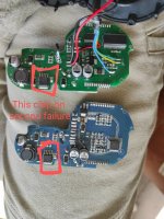
Problem is, shortly after getting it all top balanced, configured and running, after the first 10min ride the lh-100 went dead. Found some burnt circuitry, and ordered replacement. Began looking at controllers, and that's where I get really stuck.
All the documentation and advice I've come across on the web states good/bad values for resistance testing across phase to ground and phase-power, and those being steady solid numbers.
Problem I'm having when testing is I don't get steady readings, clearly capacitors are being charged by the meter during test. Hard to interpret if there's shorts or blown FETs or what.
Is it a diode maybe?
Oh, and I should add the replacement LH-100 burned up too. So it's as if the controllers are overclocking, overclocking, or bypassing regenerative current or something.
Please help
I'm fairly new to EVs but not entirely new to electronic/circuit board repair.
Here's the situation:
Scooter was brought to me with a non responsive LH-100. Determined plugs for charge port that were replaced by previous owner were different pinout, and so battery wasn't charging. Discovered in troubleshooting that the BMS had some blown FETs, so it was replaced with a BT JBD model.
Finally figured out how to get it configured to charge/discharge, and fairly certain amps, volts, etc all within listed spec of battery (it's a 60v setup).
Problem is, shortly after getting it all top balanced, configured and running, after the first 10min ride the lh-100 went dead. Found some burnt circuitry, and ordered replacement. Began looking at controllers, and that's where I get really stuck.
All the documentation and advice I've come across on the web states good/bad values for resistance testing across phase to ground and phase-power, and those being steady solid numbers.
Problem I'm having when testing is I don't get steady readings, clearly capacitors are being charged by the meter during test. Hard to interpret if there's shorts or blown FETs or what.
Is it a diode maybe?
Oh, and I should add the replacement LH-100 burned up too. So it's as if the controllers are overclocking, overclocking, or bypassing regenerative current or something.
Please help
")