Conversion of a Bultaco Sherpa

Elektrosherpa said:
After a lot of writing on Alibaba, the battery seller proposes now to send me another BMS , and instructions how to exchange it.

So now it would be highly important to know a good BMS, so that I can tell them what they have to send.
Mabye someone can tell an exact brand name / model of a BMS which would make sense to use in my build ?

Ask for the ANT BMS if possible:
this one:
https://fr.aliexpress.com/item/32826820690.html

I suggest you to go for the 300A version if possible, you can set it to whatever current you need (so you can use the 300A and set it to 150A maximum).
Try to get the little screen with it, it is really nice since it can display many informations (total voltage, voltage per cell, current draw, mileage, speed, temperatures, etc).
I think the seller will not be ok to pay the full price for it, but maybe you can give them a little extra money and split the bill.
 
I would be very worried if the cells in the battery pack are safe to deliver the kind of amps you will extract with such a BMS upgrade. Please monitor the heat in the battery pack when in use with the new BMS you will connect to it.
 
FbGFxVQhO6UHmBZQU said:
download google translate app to your smart phone if u can. it will help understand many chinese characters.

Yes, I have done some translating (not with smartphone, coz I hate the small screen to work with, but on PC)-
and I have found kind of the same meanings.
I also manged to figure out the function of the charger this way.

In the meantime, the seller seems to admit that his BMS is too weak- in his last statements on Alibaba he tried to say it is my fault by saying that I hadnt told them from the beginning what currents I want to draw from the battery.
But the whole pre-sales-chat is still available on Alibaba, and I could proof that I have told them at least 3 times that I want ~160 A permanent and ~300 A peak discharge.

As I pointed out above, the actual offer is to send me a better BMS and a video tutorial how to change it myself.

I am not yet decided what to do:
On the one hand I dont have great desire to tear that battery apart and work on it myself, only to finally get what I have already paid for, and for what I have waited almost 3 months.
On the other hand - if I change the BMS by myself, I will find out how it is done, and probably I'll do a better job than a random chinese factory worker.
 
What worries me is the cells they are using: if the cells were not sized to deliver the 300A peak then switching to a bigger BMS will not help. Sure the BMS will not cut the power, but the cells will be damaged, resulting in loss of capacity and a quick death.

Earlier in the discussion you mentionned these: 54 Ah/72 V battery, with 5c peak and 3c permanent discharge capability.
If these figures were to be correct, that would mean that your battery pack is capable to output:
-54 x 5 = 270Amps peak
-54 x 3 = 162 amps continuous

Luckily your battery has lots of capacity,
But let's hope that the cells they used actually match the figure they announce. I think you should be ok, given the large capacity of your battery pack

I think you can go on and get the BMS. It is not very easy to install it by yourself, so be prepared and take this time to binge watch some youtube video tutorials, but it is not rocket science either. You'll need to know how to weld big cables to it, so you'll need a very powerful soldering iron and to practice using it before trying on the actual BMS. It's intimidating for sure, but it is doable, no worries.
Also you'll need to program it later in order to set up all the parameters of your battery, don't hesitate to ask here, we'll help you :wink:
 
Dui said:
What worries me is the cells ...
Earlier in the discussion you mentionned these: 54 Ah/72 V battery, with 5c peak and 3c permanent discharge capability.
If these figures were to be correct, that would mean that your battery pack is capable to output:
-54 x 5 = 270Amps peak
-54 x 3 = 162 amps continuous

This is also an important point.
You quote me correctly - this is what I ordered and paid.

But considering that they sent me a battery with such a weak BMS - who tells me that the cells in the battery are what I wanted?

I have not received a data sheet or any other kind of technical information with the battery.

If you build a battery with this capacity and discharge rates, it is logical, that ALL COMPONENTS have to match these data.
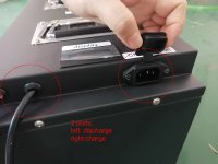
But they obviously did NOT pay attention to that: Not only the BMS is a (bad) joke, I have showed earlier the funny charge/discharge port with a C13 socket - those sockets are usually made for maximum 250V / 10 A.
 
Would you be willing to tell who your supplier at Alibaba was? I am also looking for a 72v battery and would like to avoid such a supplier if possible.
 
Wimbi39 said:
Would you be willing to tell who your supplier at Alibaba was? I am also looking for a 72v battery and would like to avoid such a supplier if possible.

Sure.
I dont see any reason to keep it secret.
It's called:
Dongguan Huanhuan Energy Technology Co. Ltd.

However I am quite sure that this is not the only provider on Alibaba with such a behaviour...

And (also to consider!!) :
From what I have experienced, the Alibaba buyer protection is generally more than poor.

No final decision made yet, but from how it went until now, I am absolutely not convinced:
For example, in the whole complaint process, I have criticized three times
that I have neither received the promised englisch manual for the charger,
nor any technical data sheet of the battery (concerning the cells and the BMS they used)-
but the "dispute moderator" of Alibaba did not react to this at all...

My next battery will be selfmade, that's for sure.
 
Just a little update of the battery story:

Still no technical data of the battery received, seller stopped doing anything.
And still no decision from Alibaba.
Last offer was 50$ refund, which I didnt accept.

I have been using the waiting time (this project consists of 50% waiting...thanks to China)
to redesign the wiring:
Since "Dui, ni shuo de dui" mentioned that this contactor stuff isn't really necessary,
I decided to throw out that complicated thing and just use two battery switches (rated 300A) instead.

This would shorten the cables from battery to controller by ~75% (from 45 cm to 10 cm)...

Could someone look over the plan and confirm (or correct) it?

WiringPlan-simplified.jpg
 
If you have a bms that you can turn off, then the negative switch is defiantly not necessary.
I dont know if I should bother with double switches either way.

However, I would probably put some sort if pre charge circuit in there. The bms might be able to handle that part. But if you want to take the load off, it would be good to have one in parallel with one of your switches.

Depending of how your system looks an alternative to switch and fuse could be an automatic fuse. Then you have both switch and fuse in one part. I dont think it is a good idea to get them wet though.
 
I dont think the shitty BMS, which my battery seller has used, can be turned off / on, or can be adjusted in some way - and even if so, I dont know how, because I havent got any documentation with it.

So let me sum up in my own words, to get it clear:

I will need a "precharge circuit", no matter if I use a "contactor" (which in my understanding is just a switch, but operated by electromagnetic coils) or a manual switch.
And this "precharge circuit" is mainly a resistor, which slows down the draw of electricity when I switch on the controller.
If I do not use such a "precharge circuit", the strong current which the controller needs for the initial charging of its capacitors can damage the contact points of any switch used for switching it on.

Is that right?

Sorry for asking so stupidly, but I have almost zero experience with electronics.
I know about domestic electrical stuff (230V AC), and regular car and motorbike 12V DC installations,
but if it comes to electronics with resistors, capacitors, transistors, diodes and so on, I am lost...
 
The ANT BMS does have a precharge system, you can even adjust its value in the software. No need to add another one :)
I would also ditch the switches, they aren't necessary since the BMS does that already.

So Basically I would wire it like that:
wer.png

The switch I added at the top is the ignition switch, the thing you turn with the key to start your bike.
 
Thanks for the drawing.
The problem is: I dont have this ANT BMS.
I have the cheap 65A BMS-thing which the seller put into the battery, and I wanted to test it as it is.
In this case I will need the precharge stuff, won't I ?


Btw-It looks like I will not get any refund or something:
The last news from Alibaba was on 10.November and said:
"Your refund application is still awaiting supplier to provide the evidence "
Since then no new messages.

When I had a look at the "case" on Alibaba, I saw that the "evidence" which the seller provided is:
I didnt tell him I want to use the battery for such a strong motor.

He claimed this although I have proven (by help of the the sales chat record)
that I repeatedly said I want a 72V/54Ah-battery with 3c/5c discharging ability.
So this obviously means:
he thought I wanted a strong battery with 3c/5c discharging just for fun, not because I need it.
And Alibaba seems to follow this funny view...

No decision made by Alibaba, no new refund or compensation offer by seller.

THEREFORE I STRONGLY ADVICE AGAINST BUYING ANYTHING AT ALIBABA !!!!
 
Elektrosherpa said:
Thanks for the drawing.
The problem is: I dont have this ANT BMS.
I have the cheap 65A BMS-thing which the seller put into the battery, and I wanted to test it as it is.
In this case I will need the precharge stuff, won't I ?


Ah ok, I thought you were buying one. In which case then yes, your drawing was correct, and yes it's better to add the precharge resistor if you plan on connecting/disconnecting your battery often.

Elektrosherpa said:
Btw-It looks like I will not get any refund or something:

No decision made by Alibaba, no new refund or compensation offer by seller.


Yeah that's kinda typical chinese behavior, they don't really like to make such decisions and they prefer to split the blame between both parties whenever possible.
It will take a while but they will take a decision eventually.
It's not easy from Alibaba standpoint, you got the battery delivered and they aren't battery experts so its hard for them to understand if your claim is legit or not. There are lots of scammers, especially in the US, who order stuff and then fill claims to get reimbursed while keeping the products.
Not saying you aren't right on this one, but from their standpoint it isn't that obvious.

Let's hope you'll win!
 
Dui said:
Ah ok, I thought you were buying one. In which case then yes, your drawing was correct, and yes it's better to add the precharge resistor if you plan on connecting/disconnecting your battery often.

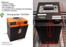
I will be obliged to disconnect the battery often, because they didnt only put a weak BMS,
but also didnt make separate charge and discharge ports (as their offer picture on Alibaba showed it, and I have ordered).
So I will have to unplug the battery each time when I want to charge it...

In their offer, the battery had a C13 socket for charging, and an Anderson connector on some 10cm cable for discharging.
The battery I got has only this ridiculous C13 socket for both.
Btw a fact which the Alibaba "mediator" has completely ignored, although I pointed this out several times...

Battery Offer and Received.jpg
 
Elektrosherpa said:
but also didnt make separate charge and discharge ports (as their offer picture on Alibaba showed it, and I have ordered).
So I will have to unplug the battery each time when I want to charge it...

In their offer, the battery had a C13 socket for charging, and an Anderson connector on some 10cm cable for discharging.
The battery I got has only this ridiculous C13 socket for both.
Btw a fact which the Alibaba "mediator" has completely ignored, although I pointed this out several times...

Battery Offer and Received.jpg

Lol no, you can charge it through the discharge port, no problem. The only thing you have to do is to connect a charging plug in parallel to your main power cables, that's all. So you just have to integrate this into your wiring harness, this way no need to disconnect anything.
One thiing is for sure: the plug you currently have on the battery won't be able to bear 150A for long, it's not made for such high current. The one on the original picture was okay.
 
Dui said:
One thiing is for sure: the plug you currently have on the battery won't be able to bear 150A for long, it's not made for such high current. The one on the original picture was okay.

That's what I told Alibaba-all the C13 sockets I have ever seen are made for a current of 10 A, some rare exceptions for 20A.
No way to discharge with 65 (as the built-in BMS allows) or 160A (as I have ordered) through this toy.
But they completely ignored this point.

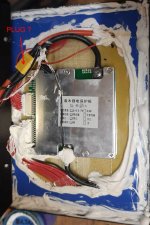
Here is again the picture of the opened battery.
Battery-inside2.jpg

The yellow thing looks like a plug - if so, I could unplug it and add double cables after the plug:
One pair for charging through the C13 socket (as it is now),
plus another pair going out of the battery case and outside equipped with an Anderson plug for serious discharging,
as the seller shows it on all of his product pictures:
BatterySeller-evidence6.jpg

Do you think this would be possible?
 
By the way:
Today I finally received the message that they refused my refund demand-
because I did not accept the "solutions" offered by the seller...

In consequence, I immediately opened a new case and re-submitted the whole load of evidence, but I am afraid this will not help.

Next, I will try to get my money back via Paypal---

*§&"@** ALibaba !!! :evil:

Big mistake to buy there.
 
Elektrosherpa said:
The yellow thing looks like a plug - if so, I could unplug it and add double cables after the plug:

Do you think this would be possible?

Yeah, totally. But if I may, a better way to do it would be to ditch this yellow plug entirely and directly solder your new wires onto the BMS terminals.
You just need a powerful soldering iron to do that (and give it plenty of time to heat up), it's not very difficult. Note that it's not your regular soldering iron, it's the big ass stuff like that: https://alitools.io/en/showcase/high-power-electric-soldering-iron-100w-150w-200w-300w-500w-220v-pure-copper-tip-external-heated-welding-equipment-tools-32655230362

But if you plan on doing this mod, you can probably consider purchasing the ANT BMS and install it instead of this one. Shouldn't take much longer if the balance wires plugs are the same. If they aren't the same then it's a bit more work and a lot more scary for unexperienced people, but it's not very complicated, just very intimidating.
Really sorry to hear that your claim was unsuccessful, it's always difficult to purchase stuff from the other end of the world.
 
Still fighting with the idiots from Alibaba.

The seller even admitted himself that the battery he sent does not match my order,
but he keeps saying that it's my fault because I havent told him that I want to use it for a motor with up to 20kW.

My argument, that the promised discharge rates of 3c/5c in a 72V/54Ah battery DO MEAN EXACTLY THAT
(3*54 = 162 A = 11664 W, 5 * 54 = 270 A = 19440 W) is permanently ignored by them.

The dispute management of Alibaba does not check anything, they just let seller and buyer tell their opinions, without making a real decision.

The "best offer" until now:
50$ refund from seller, plus "maybe" another 50$ from Alibaba, but without guarantee that this second 50$ will be really paid.
And they keep urging me to accept this offer, otherwise I wont get anything.

I repeat my advice:
DO NOT BUY ANYTHING AT ALIBABA !
 
Although I was quite sure in advance what would happen,
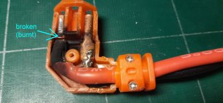
I have tried to use the garbage plug this Donguan A**hole Company provided.
(full name "Dongguan Huanhuan Energy Technology Co. Ltd.", just for you to know what you should avoid)

I did this to have a proof that they sent me garbage, and not just suspecting it.
Here is the result:

PLUG BATTERY SELLER-text.jpg

This happened when I just plugged it in- not even tried to drive.
 
In order to make this thing work,
I will add new cables inside the battery case,
drill 2 holes to bring them out,
and put a serious Anderson connector at the outside ends.

The C13 plug will be the charging port -
since they told me not to charge with more than 10 A (i.e. 0.2 C) ,
this will be OK, I guess.

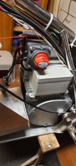
I have decided to use two manual switches in order to be able to disconnect the battery completely before plugging/unplugging the Anderson connector:
Schalter2.jpg

For not running into troubles when the connectors will be strong enough to let out some real current
(at least the 65A which the BMS is declared to support),
I am trying to understand the function of the "precharge circuit",
which several people have recommended to add.

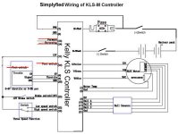
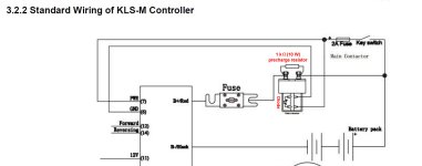
In the original wiring scheme from the QS manual, it looked like that:
Kelly-WiringPlan-KeySwitch.jpg

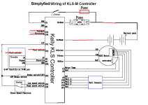
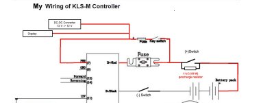
Since I am not using a contactor, as they showed it there, but just manual battery switches, I am not sure if I will need the Diode in the wiring scheme above, too - or if it will be sufficient to just put the resistor between the two connectors of the manual switch?

Then it would be like that diagram:
Kelly-WiringPlan-ManualSwitches.jpg

Actually I didnt really understand how the "precharge circuit" works-
in my understanding it is meant to limit a current rush flow in the moment of switching on,
(due to the capacitors of the controller being charged initially), which otherwise would be too high for the switch's contacts,

Is that right??

Can anybody confirm or contradict my assumption that the diode from the wiring plan will not be needed with a manual switch?

And if I need it-where to insert it?
The contacts of the contactor (coil switch), where it is located in the wring scheme, do not exist in a manual switch...
 
Elektrosherpa said:
In order to make this thing work,
I will add new cables inside the battery case,
drill 2 holes to bring them out,
and put a serious Anderson connector at the outside ends.

The C13 plug will be the charging port -
since they told me not to charge with more than 10 A,
this will be OK, I guess.

I have decided to use two manual switches in order to be able to disconnect the battery completely before plugging/unplugging the Anderson connector:
Schalter2.jpg

For not running into troubles when the connectors will be strong enough to let out some real current
(at least the 65A which the BMS is declared to support),
I am trying to understand the function of the "precharge circuit",
which several people have recommended to add.

In the original wiring scheme from the QS manual, it looked like that:
Kelly-WiringPlan-KeySwitch.jpg

Since I am not using a contactor, as they showed it there, but just manual battery switches, I am not sure if I will need the Diode in the wiring scheme above, too - or if it will be sufficient to just put the resistor between the two connectors of the manual switch?

Then it would be like that diagram:
Kelly-WiringPlan-ManualSwitches.jpg

Actually I didnt really understand how the "precharge circuit" works-
in my understanding it is meant to limit a current rush flow in the moment of switching on,
(due to the capacitors of the controller being charged initially), which otherwise would be too high for the switch's contacts,

Is that right??

Can anybody confirm or contradict my assumption that the diode from the wiring plan will not be needed with a manual switch?

And if I need it-where to insert it?
The contacts of the contactor (coil switch), where it is located in the wring scheme, do not exist in a manual switch...

Hi

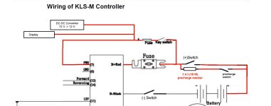
As you said that is the idea of precharge circuit and it is needed when you connect the battery to the load. Since you dont plan to use a contactor it is only needed for the fist connection and again if you disconnect the battery or the fuse. I personally added another switch in series with the precharge resistor so i can safely connect all the wires, flip the precharge switch wait a bit and then flip the bigger switch.

And no you do not need that diode. The diode is there to prevent voltage spikes from the relays coil and to protect the circuit controlling the relay.
 
kuoppis said:
Hi

As you said that is the idea of precharge circuit and it is needed when you connect the battery to the load. Since you dont plan to use a contactor it is only needed for the fist connection and again if you disconnect the battery or the fuse. I personally added another switch in series with the precharge resistor so i can safely connect all the wires, flip the precharge switch wait a bit and then flip the bigger switch.

And no you do not need that diode. The diode is there to prevent voltage spikes from the relays coil and to protect the circuit controlling the relay.

Hi "kuoppis",
thanks for your reply.

So your solution would be like this:
Kelly-WiringPlan-ManualSwitches2.jpg
(just making sure that I got it right-I am an electronics dummy, just in case you haven't noticed :D )
And this additional switch doesn't need to be able to handle high currents, right ?!
 
Back
Top